2017.06.19 FwdMan2.8.17.docx 4-31
To configure the loading unit, select UUSUUetup, then UUTUUrailer from the data collection screen.
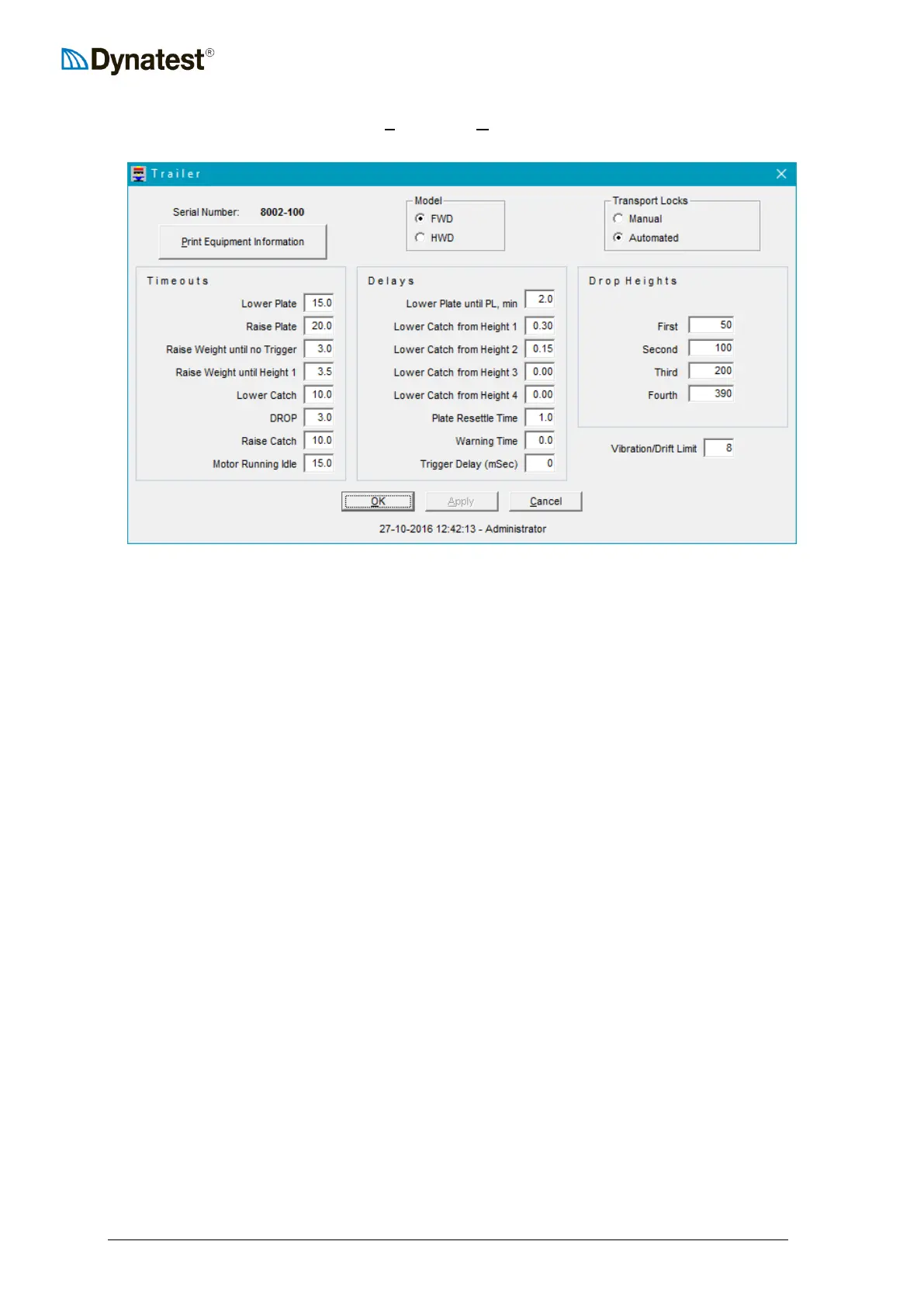
This will open the trailer setup window.
The first item to verify is the Serial Number. The serial number can be found on the
nameplate installed on every FWD/HWD unit. If the serial number does not match your
FWD/HWD, then you must exit FwdWin. At the introductory screen, click on the correct
serial number, and then return to the above window. The serial number should now be
correct.
The next item to verify or enter is the type of Transport Locks. Transport locks prevent the
FWD/HWD load plate from settling and contacting the road surface during transport. The
automated transport locks are optional and your unit may not be so equipped. The presence of
automated transport locks is easy to determine by visually inspecting the FWD/HWD
subassembly.
Timeouts are displayed in units of seconds. These timeout values are used by the computer
to monitor the status of and to control the hardware. For example, if for some reason the
FWD/HWD requires more than 15 seconds to lower the plate to the pavement surface (lower
plate = 15.0), an error message is generated by the program, indicating that some malfunction
has occurred. To assist the operator, Tooltips are provided to show the upper and lower limits
for these fields. The values shown are defaults and should not be changed unless the user has
a specific reason to do so.
Delays are also displayed in units of seconds. Default values are shown. Tooltips are provided
for each field to assist the user in entering proper values. Delay values cause the field
program to pause for the specified number of seconds prior to performing the indicated
function. For example, “Lower Catch from Height 1” is set to 0.3 seconds. This prevents the
catch from lowering to soon after weight release. If the catch is lowered too soon, it may
collide with the catch ring as the weight rebounds off the rubber buffers.
Finally, the Drop Heights must be entered or verified. The drop height unit is either mm or
inches as specified under “Options”. The values shown represent the distance from the WH
sensor to each of the four drop height stops on the subassembly. Check to make sure that the
values are correct for your System. Each time any one of the stops is adjusted, these fields
must be updated. For information on drop height adjustment, see Section 4.2 of this manual.