4) h4 should NOT EXCEED 390 mm (15-1/4”) (to ensure that the weight can be stopped
at height No. 4 BEFORE it reaches its mechanical top position, which would
otherwise result in a “premature” dropping of the weight.
NOTE that the lower a stop is placed, the greater a drop height it corresponds to.
Use a 4 mm (5/32”) Allen key wrench for the adjustment. It may be necessary to detach the
stops rail to get access to especially stop No. 3 and No. 4. Loosen a stop only so much that it
can be moved, and when tightening again, you must be careful not to damage the rail by over-
tightening.
If you want to adjust for a specific peak load level Pmax, then the following,
THEORETICAL equation may be used to ESTIMATE the corresponding drop height h in
mm:
h(mm) = (Pmax/k)
2
h(ins) = (Pmax/k)
2
/25.4 = h(mm)/25.4
k will depend on the weight setup, on the unit chosen for Pmax, and, if the metric pressure
(stress) unit kPa is chosen, k will also depend on the loading plate diameter. (In the tables
below, kPa/300 means stress in kPa using 300 mm dia. plate. For 450 mm dia. plate, the kPa
values should be divided by 2.25).
Tables 1 and 2 below apply for the FWD only.
Tables 3 and 4 below apply for the HWD only.
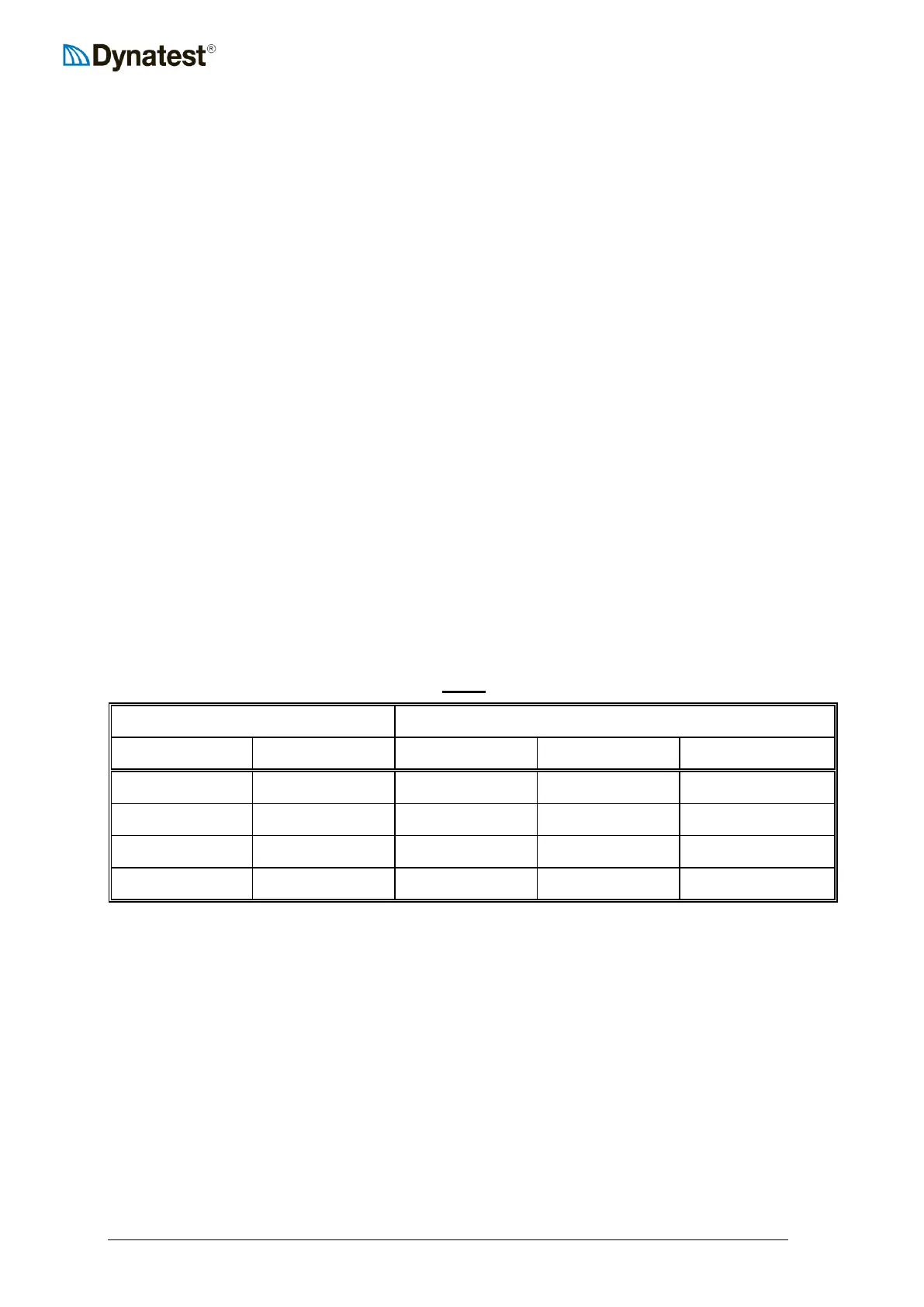
Table 1 (UUFWDUU ONLY!)
Before the drop height is calculated, it is necessary to select a weight setup (50, 150, 250 or
350 kg). To do this, use the following Table 2 showing the usable load ranges for each weight
setup: