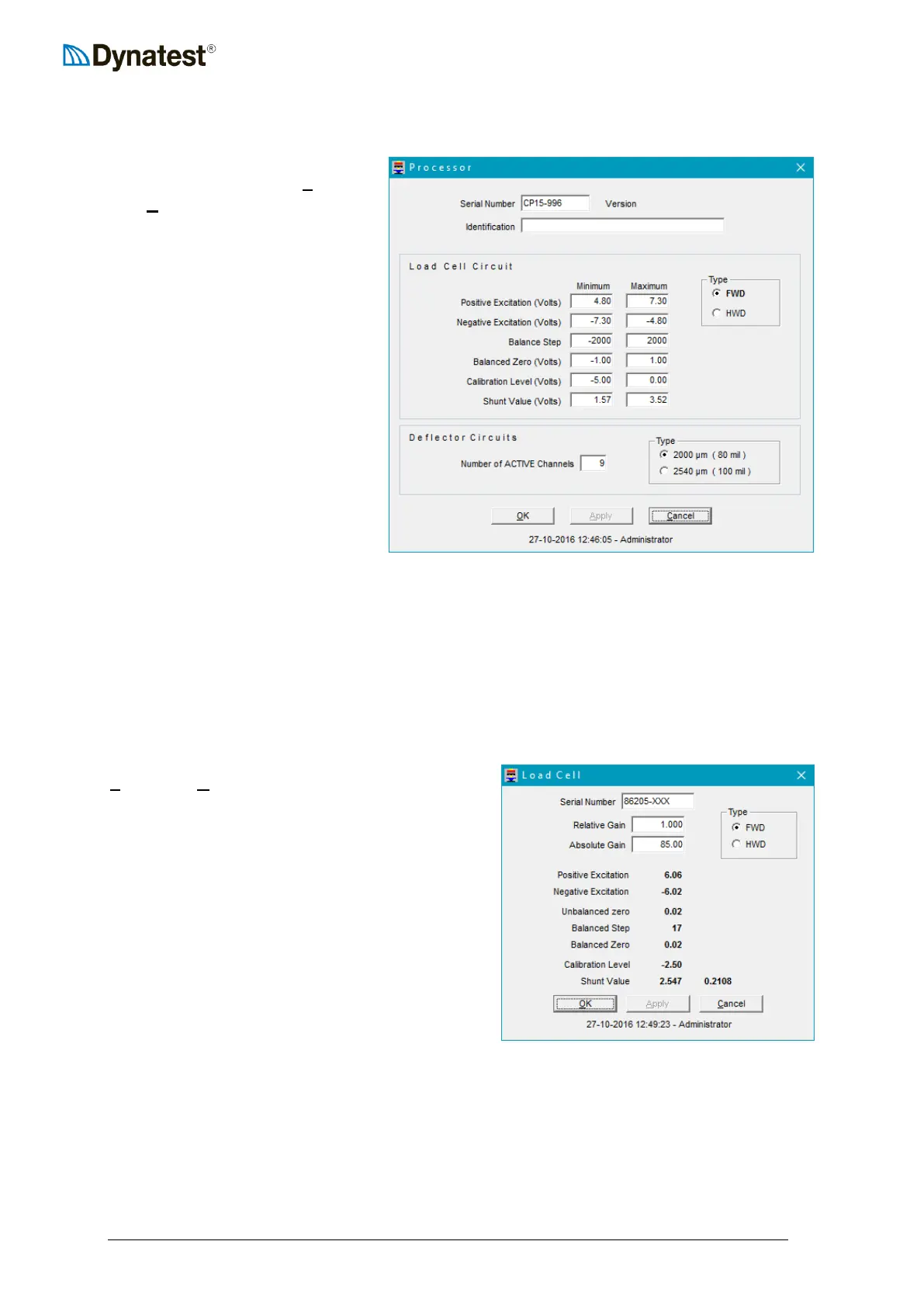
4.3.3 Compact15 System Controller
To configure the Compact15
System Controller, select UUSUUetup
then UUPUUrocessor from the data
collection screen.
The Version is retrieved from the
Compact15 System Controller and
refers to the firmware version.
The Identification field allows the
user to enter any useful
information of his choice that may
be related to the System Controller
setup.
The area of the screen labelled
Load Cell Circuit contains
operating voltage limits for a
typical load cell. These values do
not affect load cell operation. Their
purpose is to establish limits
beyond which the field program will issue an error message. To the right of these numbers,
the user can indicate whether the load cell is an FWD or HWD type.
In the Deflector Circuits area, the user can indicate the Number of ACTIVE Channels.
Note that to the right the user can also specify the maximum range of the deflectors. Dynatest
produce two types, 2000 and 2450 microns (80 or 100 mils). You should consult your
delivery documents and specifications to verify the type of deflectors provided.
4.3.4 Load Cell
To configure the Load Cell parameters, select
UUSUUetup then UULUUoad Cell from the data collection
screen. The operator should first verify or enter
the Serial Number. The user should also verify or
specify whether the load cell is mounted on an
FWD or HWD by checking the appropriate button
in the Type box.
The Relative Gain and Absolute gain
(calibration factors) are provided by Dynatest
upon delivery of the equipment or delivery of a
replacement load cell. The absolute gain can only
be changed by the user after consulting Dynatest.
The relative gain is provided to accommodate
modest changes that are required as a result of a
calibration of the load cell.
The remaining fields (Unbalanced Zero … Shunt Value) provide a real time display of load
cell voltages and other parameters. These fields are not accessible by the user.