Sequence
Prior to testing, the operator must define the sequence.
A sequence is a series of programmed tasks to be
performed by the FWD/HWD at each test point. The
sequence box allows the operator to specify the number
of steps, step types, and step parameters utilized at each
test point. It also allows the operator to enable on-
screen plotting (D) and storage of time history data (F)
for each applicable step.
A step can be any one of the following types:
1. No Op No Operation (fill)
2. Pause Waits for user action
3. Seating A drop from a specified height, data will not be stored to disk
4. Height A drop from a specified height
5. Loading The drop height is adjusted to achieve a specified target load
6. Deflection The drop height is adjusted to achieve a specified centre deflection
7. Resettle The plate is lifted of the ground and then lowered again
8. Weight Up The weight is raised to a specified height (but not dropped)
9. Catch Dn The catch is lowered (returning the weight to the hit plate)
10. Terminate Leaves the plate on the ground
3, 4, 5, 6 and 8 require a “Step Parameter”. A step parameter is a ‘modifier’ associated with
the step type. For example, “Seating” and “Height” requires that the desired height (1,2,3 or
4) is chosen (see Section 5.2-"Drop Heights Adjustment”).
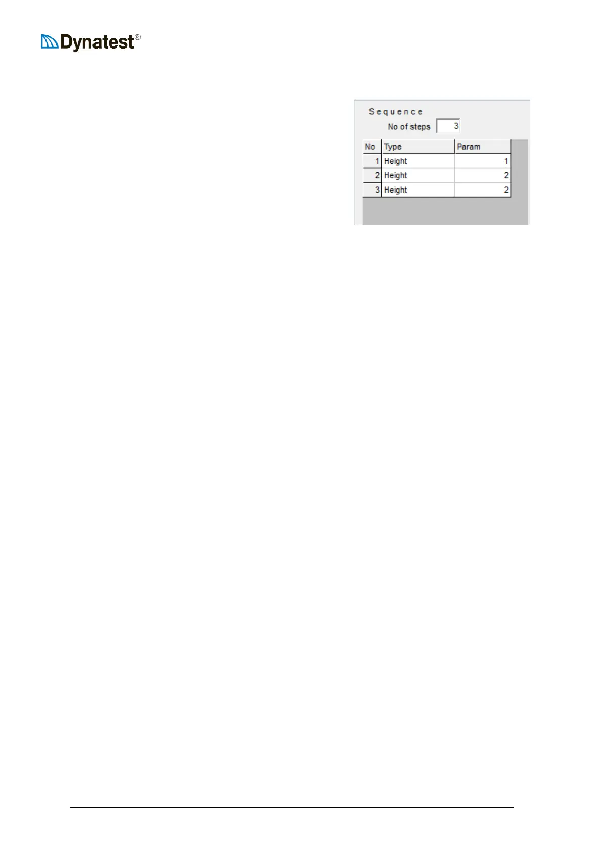
To define a sequence, the operator first enters the number of desired steps in the No of steps
box. The number of rows in the table expands or shrinks to accommodate the specified
number of steps. The leftmost column shows the step numbers.
Next, for each step, the operator must select the action to be performed. In the example
above, the operator has specified that three drops from a specified height will be performed
at each test point.
The operator then assigns a step parameter for each step type. In the example above, the
parameters are 1, 2 and 2. This will perform one drop at drop height 1 and two at drop
height 2 at each test point.
The fourth and fifth columns act as toggle (on/off) switches. If a round symbol appears in
the D column for a given step, the time history data (O-Scope) will be plotted to the screen
during the test cycle. Similarly, if a round symbol appears in the F column the
load/deflection time history for that step will be written to the data base file.