4.2
Layout of a DryExx
®
system
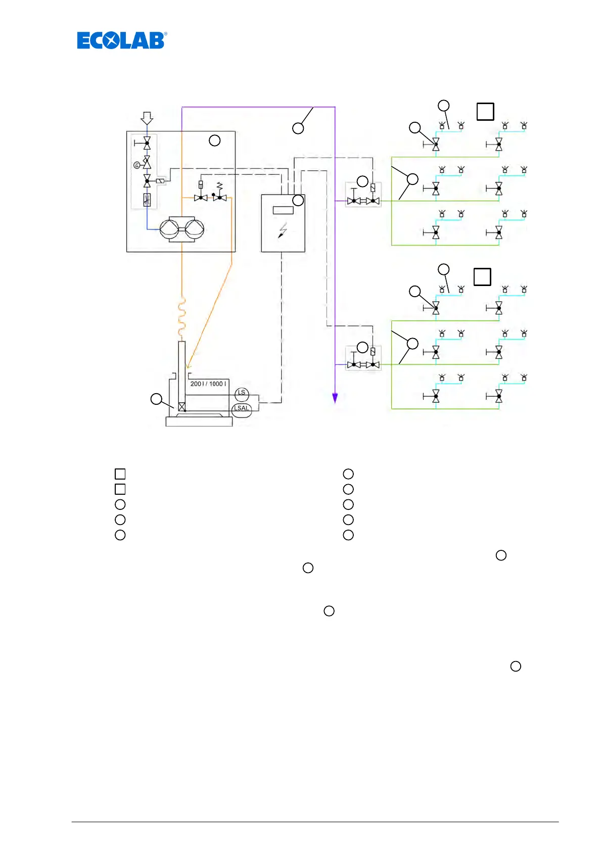
Fig. 2: Layout of DryExx system
Lubrication circuit 1
Lubrication circuit 2
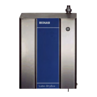
LuboDryExx metering station
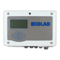
DryExx control unit
Track lubricant
Lubrication circuit valve
Distribution system connection
Distribution system
Supply line
Distribution pipe
The DryExx
®
system essentially consists of a Lubo-DryExx
®
metering station
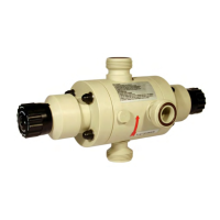
with
a compressed-air diaphragm pump, a
control unit and the standard piping and
nozzle system. V
arious types of control unit are available depending upon the size and
specification of the installation.
The branch and distribution piping system
is manufactured in stainless steel as
standard, but PE piping is available as an option. The circuit is divided according to the
requirements of the installation or installation areas; the maximum number of nozzles per
lubrication circuit is 50–60 nozzles.
The nozzle system is designed as a standard system with welded nozzle fittings
.
For conveyors with more than two tracks, the following applies for the number of nozzles
on a distribution system:
n Number of nozzles = number of transport chains - 1
The nozzles used have a throughput of approx. 3 litres per hour at a spraying pressure
of 0.2 MPa (2 bar). T
o prevent drips from the nozzles, ball valve filters with an opening
pressure of 0.14 MPa (1.4 bar) are used.
Function description
27 Ver. 08-04.2024
 Loading...