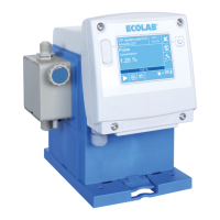
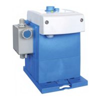
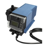
13.3 Pump key ‘EcoAdd’
The pump key comprises four groups:
n Group I: Control unit:
Ä
Chapter 13.3.1 ‘Pump key Group I - "Control unit" [EcoPro|E|S]’ on page 185
n Group II: Pump head:
Ä
Chapter 13.3.2 ‘Pump key group II - "Pump head" [01110S|D|F|C|0|0|S]’
on page 186
n Group III: Housing/driver unit:
Ä
Chapter 13.3.3 ‘Pump key group III - "Housing/driver unit" [1|S]’ on page 187
n Group IV: Packaging/accessories:
Ä
Chapter 13.3.4 ‘Pump key group IV - "Packaging/accessories" [S|0]’ on page 187
Example:
Control unit Pump head Housing/driver unit Packaging/accessories
1 2 3 4 5 6 7 8 9 10 11 11 13 14
EcoAdd E S 01110S D F C 0 0 S 1 S S 0
Complete key: EcoAdd ES-01
110S-DFC-00S-1S-S0
13.3.1 Pump key Group I - "Control unit" [EcoPro|E|S]
Elements of the “control unit” pump key:
No. 1 ‘Pump name/electrical version’
EcoAdd
Buttons/settings/display: On/off, 4 viscosity modes, 5 operating modes, 1:100, touch display
Operating modes: Manual, pulse, power, timer, batch
Inputs: Enable, pulse, power, batch
Outputs: Stroke signal, alarm
Communication: USB, CAN bus
Options: “Bluetooth” extension module
No. 2 ‘Mains supply connection’
E
Key: Description:
E 2.5 m mains cable with European plug
U 2.5 m mains cable with US plug
N 2.5 m mains cable without mains plug (with wire end ferrules)
No. 3 ‘Control unit version’
S
Key: Description:
S Standard
T Rotated control unit
C With protective cover (Eco Pro)
B With Bluetooth extension
Technical data
185 Rev. 2-05.2018