STP-iX457/iXU457 Series Turbomolecular Pump
MT-86E-001-F
Page v
PAGE
v
ILLUSTRATIONS
Figure Title Page
1 STP pump installation warning label 6
2 Hot surface warning label 6
3 Heavy product caution label 7
4 High voltage device caution label 7
5 Rotation instruction label 7
6 Cross sectional view of the STP pump 8
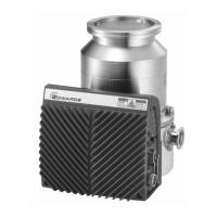
7 External appearance of STP-iX457 13
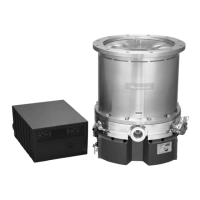
8 External appearance of STP-iX457C 14
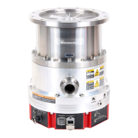
9 External appearance of STP-iXU457 15
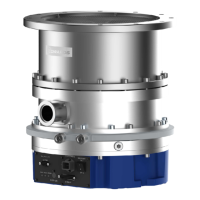
10 External appearance of STP-iXU457C 16
11 Label affixing positions 17
12 Space around the STP pump 21
13 Space around the STP pump
(with air-cooling unit [optional accessory]) 21
14 Example of lifting the STP pump 23
15 Example of lifting the STP pump (horizontal positioning) 24
16 Jack-up the STP pump 25
17 Control unit bottom face 25
18 STP pump with eyebolts 26
19 Configuration of the STP pump 27
20 Control unit 28
21 Installation of the STP pump to the vacuum equipment 30
22 STP pump installation positions 32
23 Positions of the outlet port on the horizontally
or slanted installed STP pump 32
24 Example of securing the STP pump
(when securing the inlet port with bolts) 34
25 Example of securing the STP pump
(when securing the inlet port flange with claw clamps) 35
26 Example of securing the STP pump
(when installing the damper in the inlet port flange) 36
27 Recommended leg for securing base 37
28 Screw holes for securing the base 37
29 Rotation stopper 38
30 DC power cable 41
31 Vent valve connection 42
32 Example of a control method
when introducing the atmosphere (in dashed line) 43
33 Height of purge port 46
34 Baking heater installation position 47
35 Air-cooling unit 48
36 Installation procedure for air-cooling unit U1-86 49
37 Pump operation method 56
38 Flash pattern of STATUS 58
39 X2 REMOTE connector 59
40 X2 REMOTE input signal pins (contact input) 61
41 X2 REMOTE Pin function matrix for input signal
(Type-A PROG-IN) 62
42 X2 REMOTE Pin function matrix for input signal
(Type-B PROG-IN) 62

 Loading...
