◦ Cw = 2.4 (for unknown shapes).
◦ Cw = 2 (for parallelepiped/cube shape loads).
◦ Cw = 1 (for cylindrical shape loads).
◦ Cw = 0.4 (for special loads).
• P - Load
This is the load value to lift in tonnes (t).
• Ap - Downwind load area
This value is the downwind area of the load to lift in m
2
.
The operator must do this calculation before lifting operations to determine the maximum
permitted wind speed:
1. Calculate the ratio between the load (P) and the downwind load area (Ap):
P
Ap
a. If it is 2 or more than 2, refer to the TABLE A and TABLE B to lift the load.
b. If it is less than 2, go to the next step.
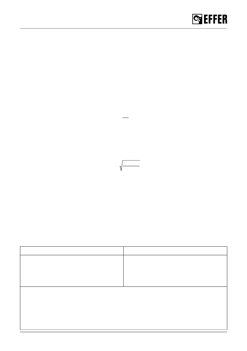
2. Calculate the wind speed reduction coefficient (Cr):
Cr =
P ⋅ 1.2
Ap ⋅ Cw
a. If Cr is 1 or more than 1, refer to the TABLE A and TABLE B to lift the load.
b. If Cr is less than 1, go to the next step.
3. You must decrease the permitted wind speed value ('V
table
'), shown in TABLE A and TABLE B,
by multiplying it by the reduction coefficient (Cr).
V
max
= V
table
⋅ Cr
Example of the calculation:
Load data Wind conditions
• Shape: cylindrical load
• Diameter (D) = 3 m
• Load height (h) = 3 m
• Weight (P) = 2 t
Values in the tables ('V
table
') for a height
operation (H) of 10 m:
• Average speed = 36 Km/h
• Gust speed = 50 Km/h
First of all, calculate the main factors Cw and Ap:
• Cw = 1
• Ap = D * h = 3 * 3 = 9 m
2
Then:
1. Calculate the ratio between the load (P) and the downwind load area (Ap):
Safety precautions and warnings
EFFER 265-315-395-525 Progress 2.0 CE 23