Optimum position
The weight that your crane can lift will be determined by:
• Stability test of your crane on the vehicle.
• Stabiliser extensions positioned and legs pressed to ground.
• The reach at which you are working and the optimum position of the boom.
• The optimal position for your crane is on the load plate.
DANGER
Never exceed the maximum weight on the load plate.
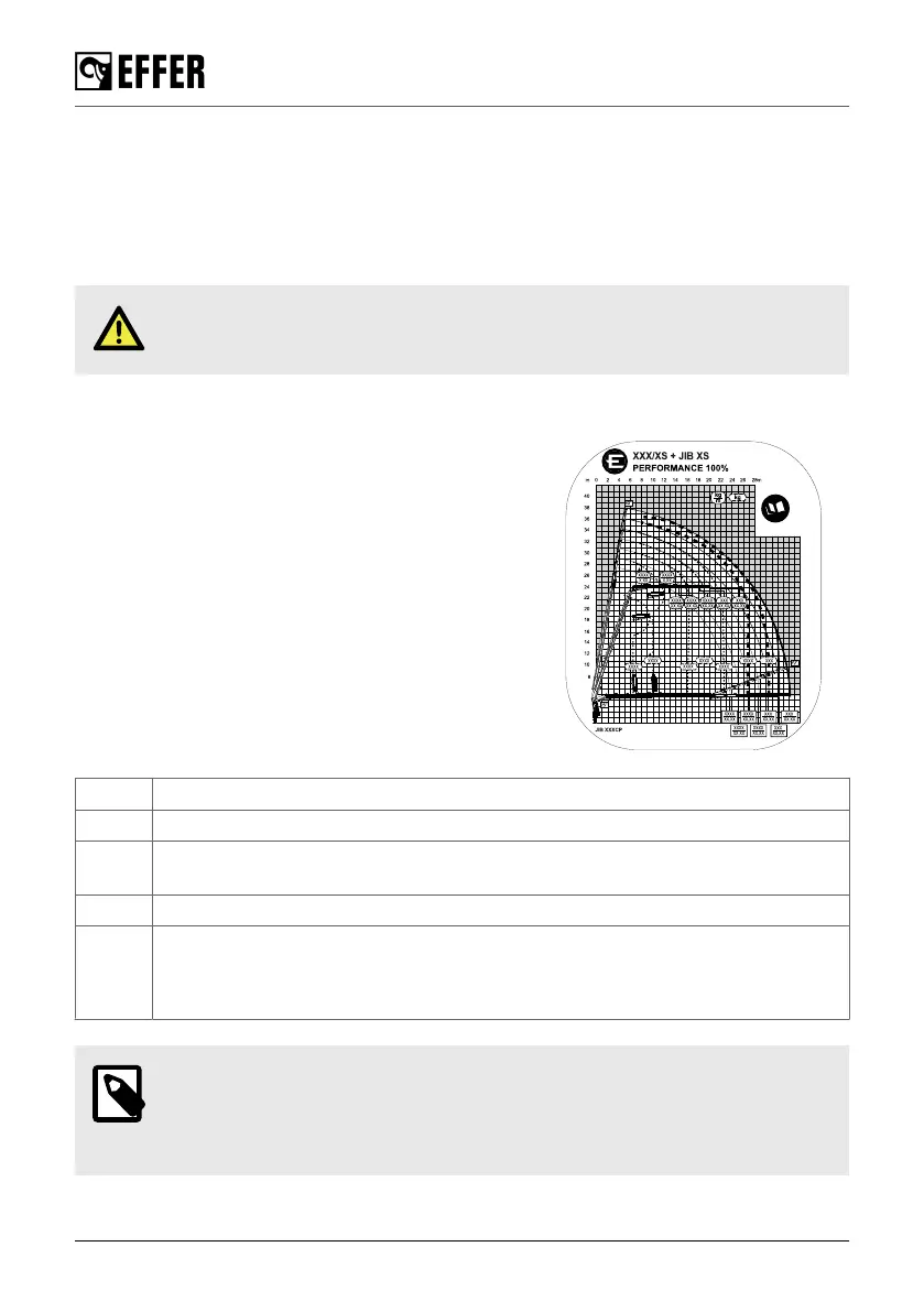
Load diagram
The load diagrams show the maximum loads your crane /
JIB (if fitted) / hoist (if fitted) may lift in the entire working
zone (manual extensions excluded). The load diagram
drawing will also be found in the Technical Data.
The white area is the working zone of the crane.
The load curves show the maximum load that may be lifted
at a given outreach and height. For a given maximum load,
the possible working zone is to the left of the load curve.
The lifting capacity for some cranes is limited in the high
lifting area.
Sometimes to lift the maximum loads, you must apply a
special hook or a locking device of the extensions. A mark
(∗, ∎, ⚫, ▲) in the load diagram next to the capacity value
indicates where this is necessary.
∗ Lifting by fixed hook.
∎ With a special hook.
∎ Maximum load of cranes / JIB limited by maximum hook coupling and/or connection
capacity.
⚫ Maximum load that can be lifted by mechanically locked extensions.
▲ 2nd boom and/or JIB not more than -30º below the horizontal. (For 2nd boom/JIB
angles greater than -30º, boom extensions must be mechanically locked).
For the crane EFFER 1000, this value is -20º.
NOTE
When the feature HSS is activated, the maximum performance could be reduced
in vertical positions from the values shown in the load diagram. Deactivate this
feature to avoid this situation.
Safety precautions and warnings
30 EFFER 265-315-395-525 Progress 2.0 CE