24. TEMPERATURE SENSORS
The system may be equipped with on-board temperature sensors and/or wireless devices with built-in temperature sensors intended for
temperature measurement in the surrounding areas. This feature allows to monitor the temperature of up to 8 dierent areas in real-time
and receive a notication by SMS text message to the listed user phone number and/or monitoring station’s middle-ware when the set
temperature thresholds are exceeded. The temperature is measured at 0,5 degree centigrade (°C) accuracy and automatically rounded to
the higher value when 0,5 or above, e. g. temperature ranging from 23,5°C through 24,4°C will be treated as 24°C. For this purpose you may
use the on-board temperature sensors or the built-in temperature sensor of the following wireless devices:
• EWP2 – wireless motion detector.
• EWKB4 - wireless keypad.
• EWP3 – wireless motion detector.
• EWD2 - wireless magnetic door contact/shock sensor/ood sensor.
• EWD3 - wireless magnetic door contact/shock sensor/ood sensor.
• EWS3 – wireless indoor siren.
• EWS2 – wireless outdoor siren.
• EWF1 - wireless smoke detector.
• EWF1CO - wireless smoke and CO detector.
• EW2 - wireless zone and PGM output expansion module (an external temperature sensor (-s) must be connected to EW2 for this pur-
pose).
• EWM1 - wireless power socket.
24.1. Adding, Removing and Replacing On-Board Dallas Temperature Sensors
To add a temperature sensor to the system, do the following:
a) Shut down the system.
b) Wire up the temperature sensor to the 1-Wire interface terminals (see 2.3.5. Temperature Sensor and iButton Key Reader for
temperature sensor wiring diagram).
c) Power up the system.
d) Run ELDES Conguration software, check if the temperature sensor has been recognized by the system and assign it to the desired
temperature sensor slot.
e) If more than one temperature sensor is required, shut down the system again and wire another sensor in parallel to the previous one.
By default, the rst added temperature sensor will be identied as primary and the second one – as secondary temperature sensor (see
24.2. Primary and Secondary Temperature Sensors).
f) Repeat the procedure as mentioned in steps from a) to d).
g) Add as many temperature sensors as necessary – wire up one after another in parallel – until the number of 8 sensors is reached.
To view the real-time temperature values measured by each temperature sensor, please refer to the following conguration methods.
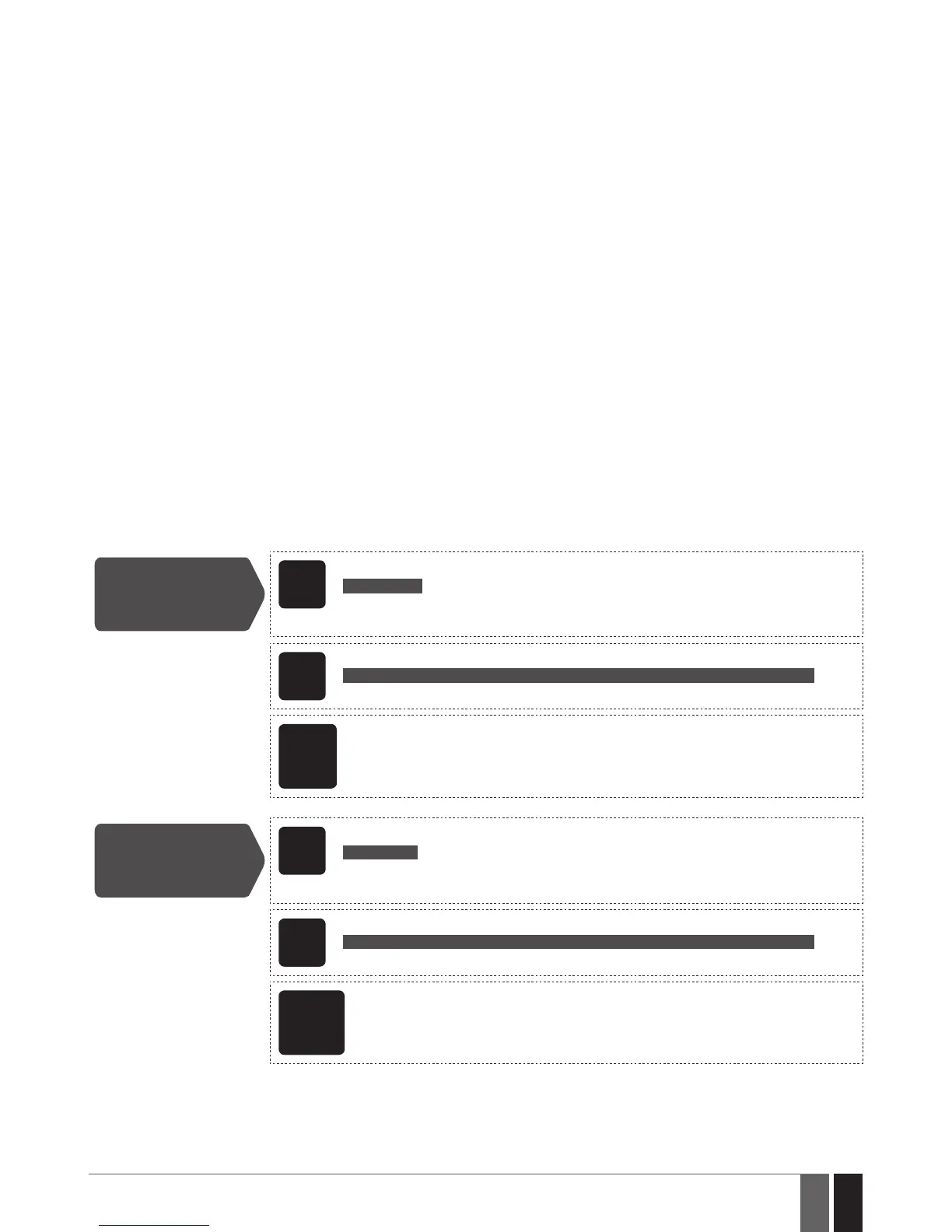
View real-time
temperature values
of individual
temperature sensor
SMS
SMS text message content:
ssss_ITEMP:ts
Value: ssss – 4-digit SMS password; ts – temperature sensor slot, range - [1... 8].
Example: 1111_ITEMP:4
EKB2
Menu path:
OK → uumm → OK → TEMP SENSORS INFO → OK → 1. tm.p C (PRIM) | (SEC)... 8. tm.p C
Value: uumm - 4-digit user/master code; tm.p – real-time temperature value.
ELDES
Cong-
uration
software
This operation may be carried out from the PC using the ELDES Conguration software.
View real-time
temperature values
of all temperature
sensors
SMS
SMS text message content:
ssss_ITEMP:?
Value: ssss – 4-digit SMS password.
Example: 1111_ITEMP:?
EKB2
Menu path:
OK → uumm → OK → TEMP SENSORS INFO → OK → 1. tm.p C (PRIM) | (SEC)... 8. tm.p C
Value: uumm - 4-digit user/master code; tm.p – real-time temperature value.
ELDES
Cong-
uration
software
This operation may be carried out from the PC using the ELDES Conguration software.
If an on-board temperature sensor is faulty, it is recommended to remove it or replace it by a functional sensor. In order to assign the tem-
perature sensor slot of the damaged temperature sensor to the new temperature sensor, please follow the procedure:
a) Shut down the system.
b) Disconnect the faulty temperature sensor and replace it with a new one.
c) Power up the system.