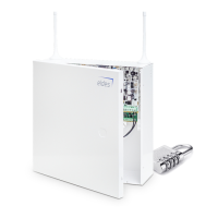
EN
ESIM384 Installation and Conguration Manual v1.1
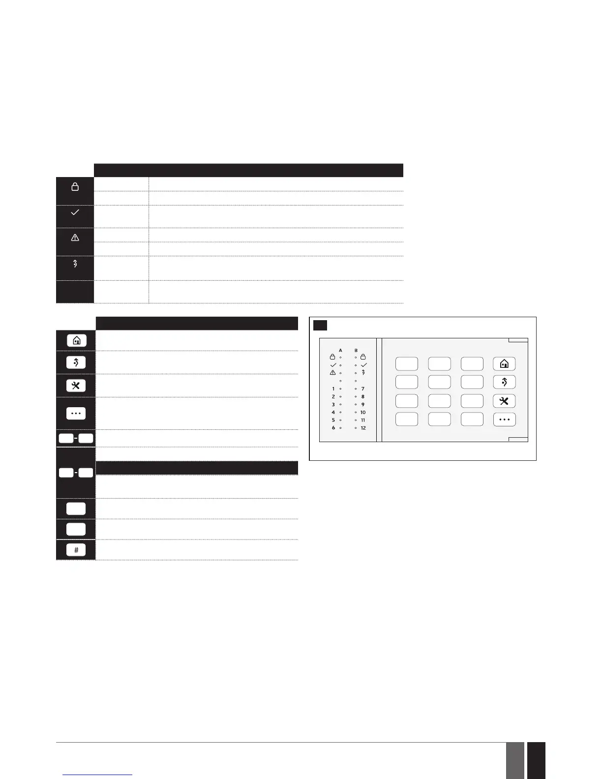
32.1.2. EKB3 - LED Keypad
Main features:
• Alarm system arming and disarming (see 12.4. EKB3 Keypad and User/Master Code).
• Arming and disarming in Stay mode (see 15. STAY MODE).
• System parameter conguration (see 5. CONFIGURATION METHODS).
• PGM output control (see 18.4. Turning PGM Outputs ON and OFF).
• Visual indication by LED indicators (see 32.1.2.1. LED Functionality).
• Audio indication by built-in buzzer.
• Keypad partition switch (see 23.3. Keypad Partition and Keypad Partition Switch).
For more details on technical specications and installation, please refer to the latest user manual of the device located at
www.eldesalarms.com
32.1.2.1. LED Functionality
INDICATION DESCRIPTION
(red)
Steady ON System armed / exit delay in progress
Flashing Conguration mode activated
(green)
Steady ON System is ready – no violated zones and/or violated tampers exist
(orange)
Steady ON System faults exist
Flashing Violated high-numbered zone
(orange)
Steady ON Violated zone bypassed
112
(red)
Steady ON Zone violated / conguration command being typed in
32.1.2.2. Keys Functionality
DESCRIPTION
48
FRONT SIDE
1st character for STAY-arming
1st character for violated zone bypass and bypassed
zone activation
1st character for Configuration mode activation or
deactivation
1st character for system fault list indication / 1st
character for violated high-numbered zone indication /
1st character for violated tamper indication
Command typing
4
1
Keypad partition switch
LED indication
Steady ON: partition armed
Flashing: partition violated
Simultaneous 4-partition arming
*
Clear typed in characters
Typed in command confirmation
32.2. 1-Wire Interface
1-Wire interface is used for the system to communicate with an iButton key reader and up to 8 temperature sensors. 1-Wire interface COM
and DATA terminals are ground and data respectively. When connecting single or multiple temperature sensors, the +5V terminal must be
used along.
For more details on 1-Wire device wiring, please refer to 2.3.4. iButton Key Reader and Buzzer and 2.3.5. Temperature Sensor and
iButton Key Reader.
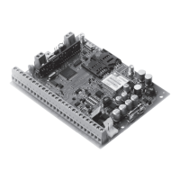
32.3. Modules Interface
The system might be equipped with modules interface slots thus enabling to use one of the following devices at a time:
• EPGM8-hardwiredPGM outputexpansionmodule(formoredetailsontechnicalspecicationsand installation,pleaserefertothe
latest user manual of the device located at www.eldesalarms.com)
• EA1-audiooutputmodule(see 32.2.1. EA1 - Audio Output Module)
• EA2-audiooutputmodulewithamplier(see32.2.2. EA2 - Audio Output Module with Amplier)