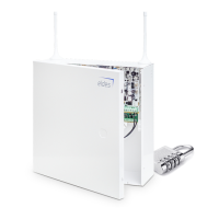
EKB3/
EKB3W/
EWKB4
1. Steady ON or ashing indicator represents certain system faults. For more details, please refer to the following table below.
Indication Description
Steady ON One or more tampers are violated; other system faults (see below)
Flashing One or more high-numbered zones (Z13-Z80) are violated (see below)
2. In order to nd out more on a certain system fault, please enter the following command.
View system faults
Enter command:
#
After this procedure the keypad will illuminate red indicators for 15 seconds. The description of each indication is provided in the
table below.
LED # Description
1 Mains power is lost
2 Low backup battery power - backup battery voltage is 10.5V or lower
3 Backup battery is not present or the battery voltage runs below 5V
4 Backup battery requires replacement - backup battery resistance is 2 or higher
5 Wired siren is disconnected/broken
6 Wireless signal is blocked by jammer
7 One or more tampers are violated (see step #4)
8 Date/time not set
9 One or more high-numbered zones (Z13-Z80) are violated (see step #3)
10 GSM connection is lost / Communication with monitoring station failed
11 GSM/GPRS antenna is disconnected/broken
12 Wireless antenna is disconnected/broken
3. In order to nd out the violated high-numbered zone, please enter the following command and refer to the table below.
View violated high-
numbered zones
Enter command:
1
4. In order to nd out which particular tamper is violated, please enter the following command. In case there is a combination of
ashing and illuminated red indicators on the keypad, please refer to the table below in order to nd out the violated high-num-
bered tamper (Tamper 13 - 80).
View violated tampers
Enter command:
2
The following table provides the combinations of red indicators belonging to a certain indicator section (A or B) on the keypad.
The combination of the ashing red indicator in section A and illuminated (steady ON) red indicator in section B represents the
respective number of a violated high-numbered zone or tamper.
B (steady ON)
A (ashing)
LED #7 LED #8 LED #9 LED #10 LED #11 LED #12
LED #1 Z13 Z19 Z25 Z31 Z37 Z43
LED #2 Z14 Z20 Z26 Z32 Z38 Z44
LED #3 Z15 Z21 Z27 Z33 Z39 Z45
LED #4 Z16 Z22 Z28 Z34 Z40 Z46
LED #5 Z17 Z23 Z29 Z35 Z41 Z47
LED #6 Z18 Z24 Z30 Z36 Z42 Z48