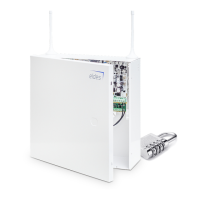
ME1 METAL CABINET CONTAINING ALL COMPONENTS
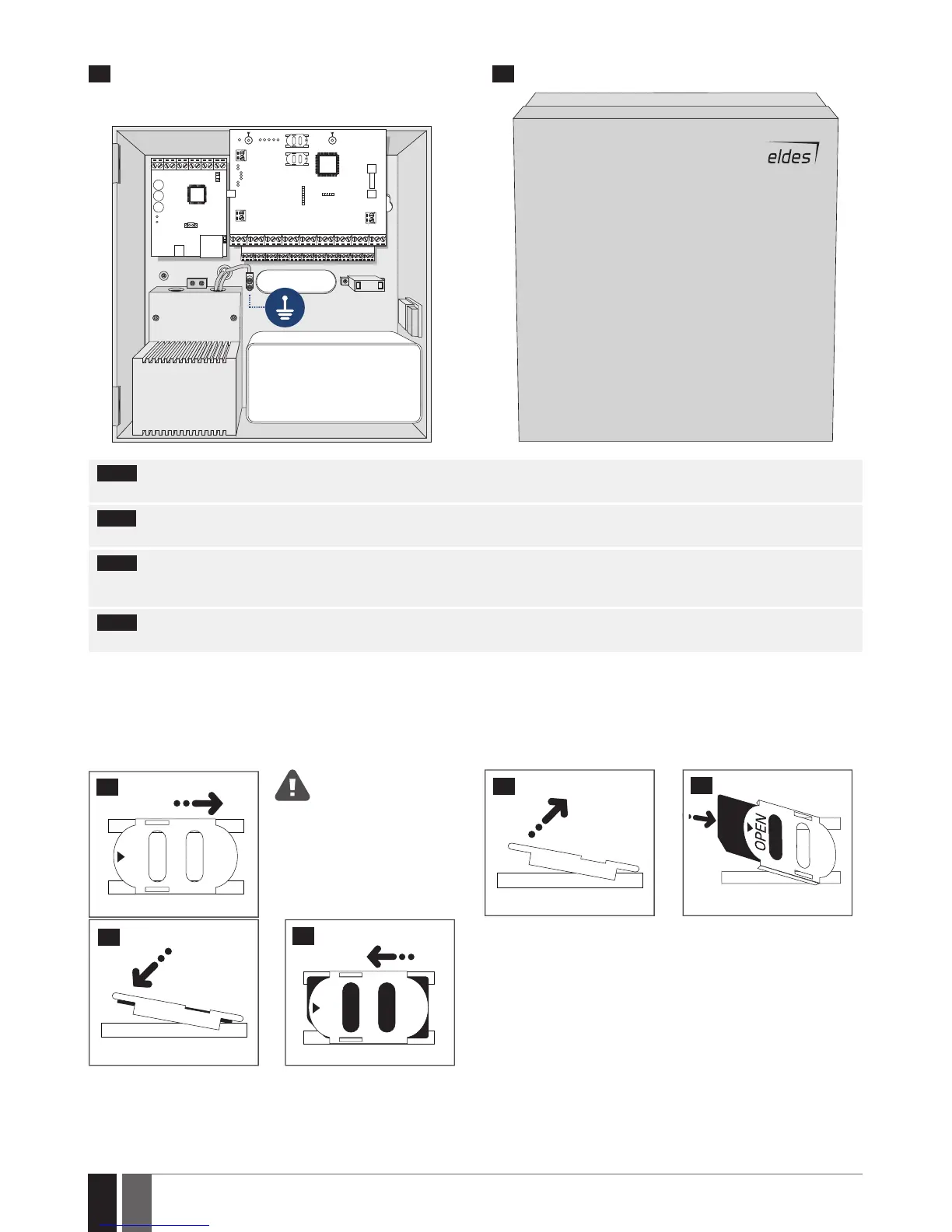
OPENOPEN
12 V BATTERY
TRANSFORMER
20 21
NOTE: The standard ME1 metal cabinet does NOT contain all of plastic standos, the quantity and the type of which depends on your addi-
tionally acquired device.
NOTE: Insert the plastic standos into the appropriate mounting points and x the circuit board of selected device on the holders as indicated
above (in pics on page 25).
NOTE: In order to appropriately install EPGM1 module, please install it in the rst place and ESIM384 alarm system afterwards. EPGM1 must
be mounted on shorter plastic standos, while ESIM384 and ELAN3-ALARM – on the longer ones. The mounting points of EPGM1 module and
ESIM384 system are indicated in pics on page 25.
NOTE: You also may wire up the accessories, such as keypads, zone and PGM output expansion modules, ELAN3-ALARM module, tempera-
ture sensors. If you choose to install the buzzer, it must be closer to iButton key reader in order to hear the exit delay countdown.
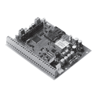
1. Disable the PIN code of the SIM card by inserting it into a mobile phone and following the proper menu steps. Ensure that the addition-
al services, such as voice mail, call forwarding, report on missed/busy calls (“call catcher”) are disabled on the SIM card. For
more details on how to disable these services, please contact your GSM operator.
2. Once the PIN code is disabled, place the SIM card into the SIM CARD1 slot of the alarm system. If Dual-SIM feature is to be used, insert
another SIM card into the SIM CARD2 slot. For more details, please refer to 31. DUAL-SIM MANAGEMENT.
Inserting a SIM card into SIM
CARD1 slot is mandatory as it is
the main SIM card slot, while us-
ing a SIM card in SIM CARD2 slot is
optional.
OPEN
22
23
24
25
OPEN
26