PI-135 OPERATOR’S MANUAL
30
Under Controls click the SET button next to cal i bra tion.
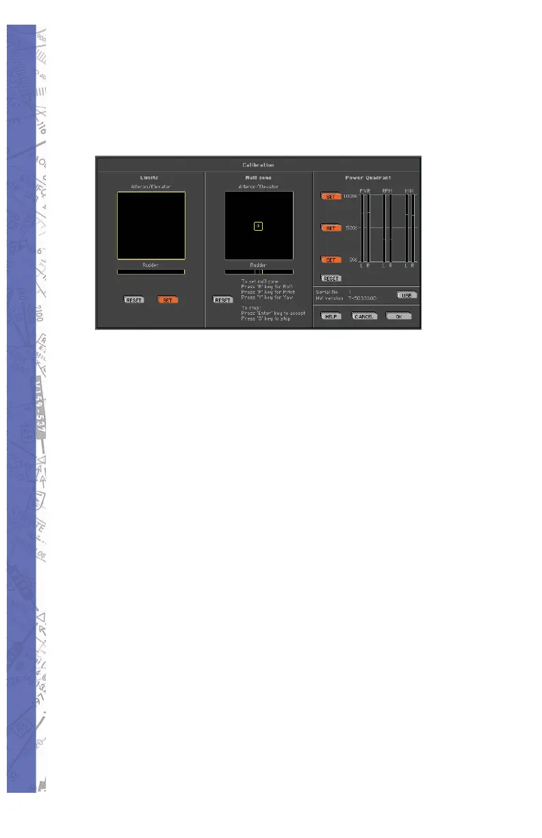
The Calibration screen is di vid ed into three sec tions or
“panels.” From left to right these are; Lim its, Null zone, and
Power Quadrant re spec tive ly.
Follow these instructions to properly cal i brate your fl ight
con trol device(s):
LIMITS
Under Limits, click the RESET but ton. No tice the small
cross-hairs in the box just be low “Ai le ron/El e va tor.” Now
move your yoke or stick through its FULL range of motion,
i.e. for ward (down) el e va tor, back (up) elevator, FULL left
and right ai le ron. The cross-hairs have now traced a blue
box graph i cal ly rep re sent ing the lim its of the con trol device
be ing used. If rudder pedals are connected, apply FULL
left and right rud der. You will see a small ver ti cal line move
with the application of rudder input. Click SET to store the
new limits settings.
NULL ZONE
The center Null Zone panel allows the user to defi ne
a “box” within which the control device(s) is considered
centered. If a fl ight control does not phys i cal ly return exactly
to center but is still with in the lim its of the “box” defi ned
under the Null Zone panel, no fl ight com mand in put will be
sent to the soft ware. Some experimentation with different
Null zone set tings may be necessary to achieve optimum