Integratethemeterwiththecontrolsystem
TheprimaryreasontodisableModbusASCIIsupportistoallowyoutousethefullrangeof
ModbusaddressesthatareavailableforyourModbusconnections(1to127).IfModbusASCII
supportisenabled,youarelimitedtousingthefollowingModbusaddresses:1–15,32–47,
64–79,and96–110.
2.SetModbusAddresstoavaluebetween1and127,excluding111.(111isreservedfortheservice
port.)
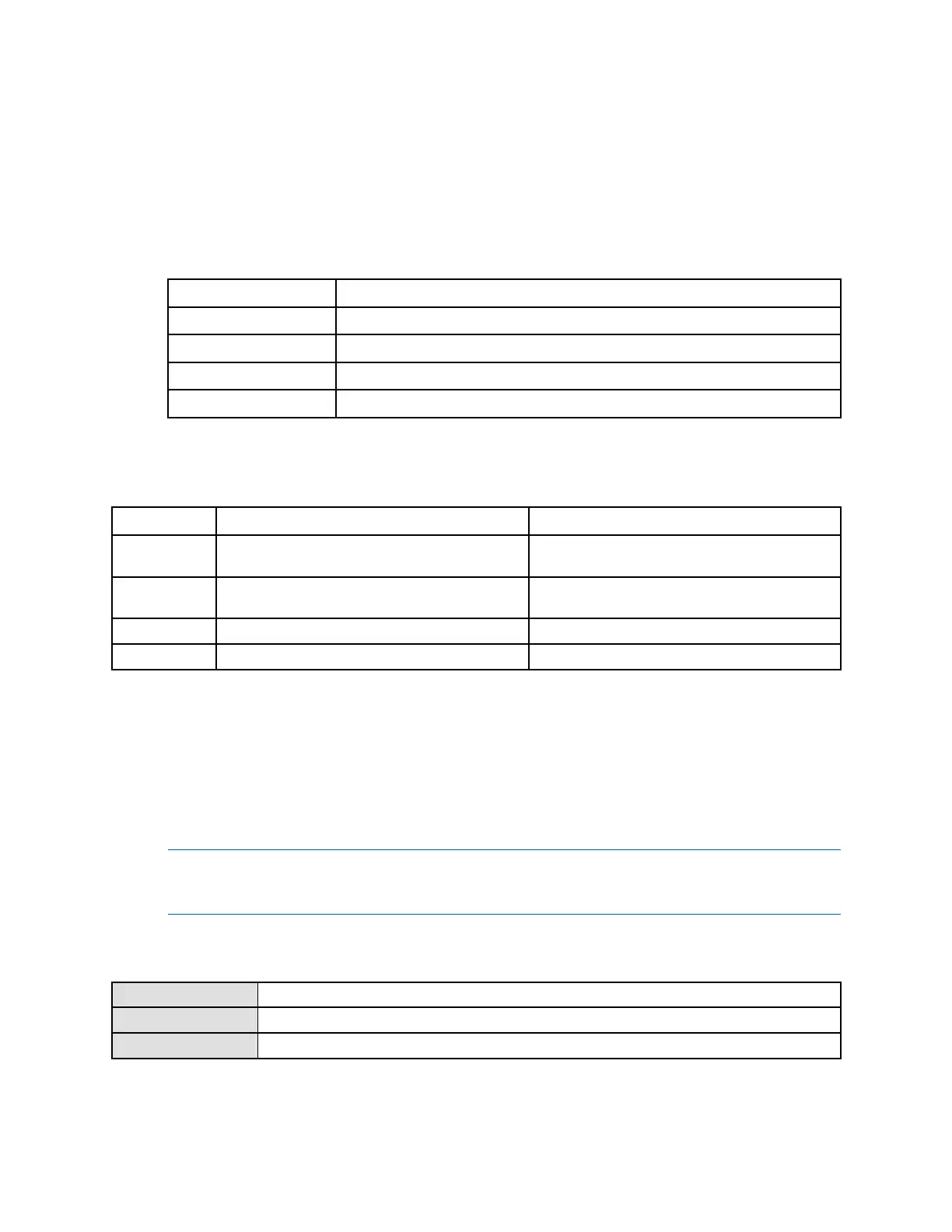
3.SetFloating-PointByteOrdertomatchthebyteorderusedbyyourModbushost.
CodeByteorder
01–23–4
13–41–2
22–14–3
34–32–1
Thebitstructureofbytes1,2,3,and4isshowninT able7-14.
Table7-14Bitstructureoffloating-pointbytes
ByteBitsDefinition
1
SEEEEEEES=Sign
E=Exponent
2EMMMMMMME=Exponent
M=Mantissa
3MMMMMMMMM=Mantissa
4MMMMMMMMM=Mantissa
4.(Optional)SetAdditionalCommunicationsResponseDelayin“delayunits.”
Adelayunitis2/3ofthetimerequiredtotransmitonecharacter,ascalculatedfortheserialport
currentlyinuseandthecharactertransmissionparameters.Validvaluesrangefrom1to255.
AdditionalCommunicationsResponseDelayisusedtosynchronizeModbuscommunicationswithhosts
thatoperateataslowerspeedthanthetransmitter.Thevaluespeciedherewillbeaddedtoeach
responsethetransmittersendstothehost.
Tip
DonotsetAdditionalCommunicationsResponseDelayunlessrequiredbyyourModbushost.
7.6.4ConfigureDigitalCommunicationsFaultAction
DisplayNotavailable
ProLinkII
ProLink→Conguration→Device→DigitalCommSettings→DigitalCommFaultSetting
FieldCommunicatorCongure→AlertSetup→Inputs/OutputsFaultActions→DigitalCommunications
DigitalCommunicationsFaultActionspeciesthevaluesthatwillbereportedviadigitalcommunicationsifthe
transmitterencountersaninternalfaultcondition.
144
MicroMotion9739MVDTransmitters

 Loading...


