4900002277 J22 TDLAS Gas Analyzer
22 SpectraSensors, Inc.
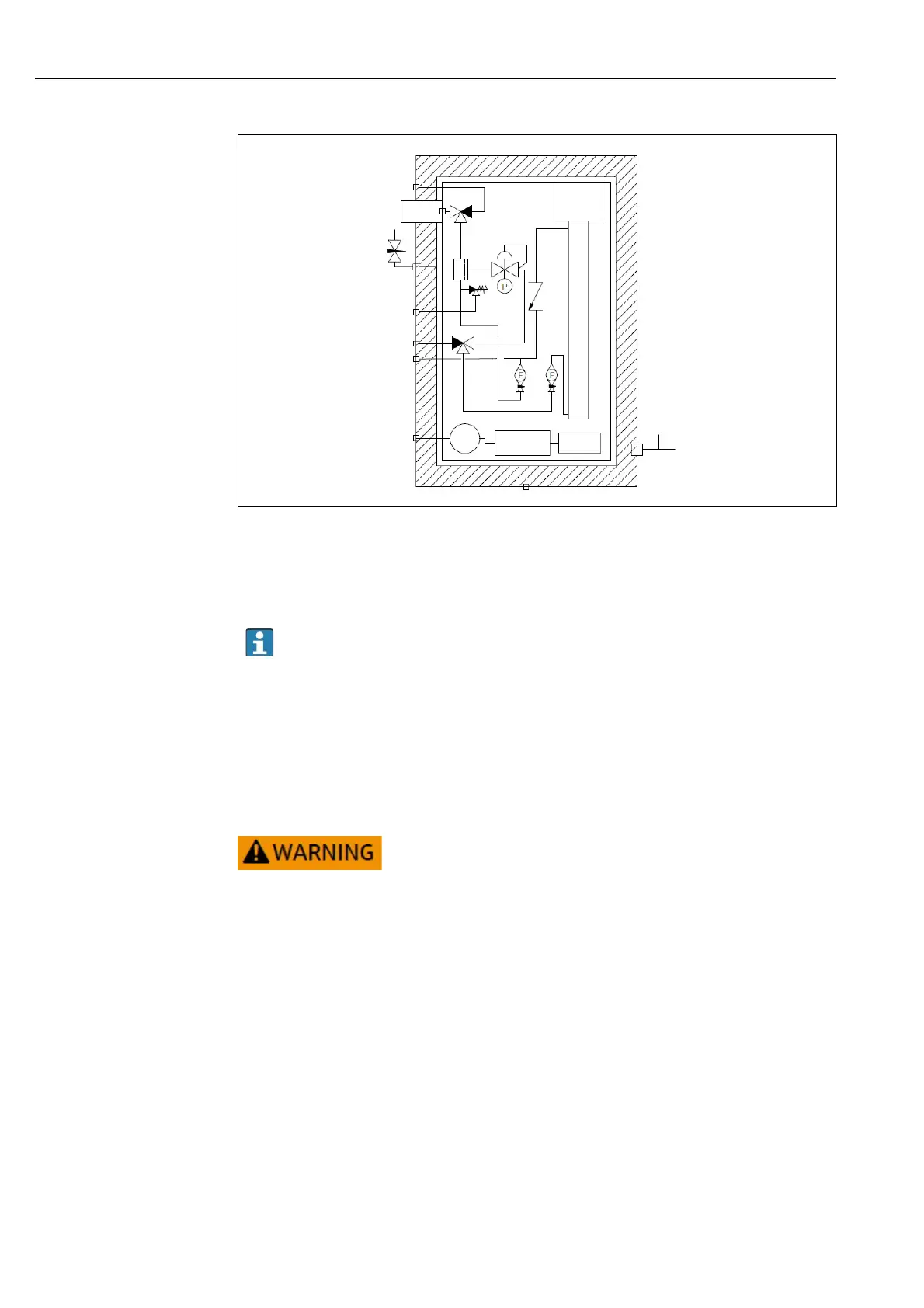
2: J22 TDLAS Gas Analyzer flow diagram - sample system
1 Pressure gauge
2 Sample supply valve (2- or 3-way)
3Flow meter
4Flow meter
For systems with an optional sample system enclosure purge, run purge before
start-up
→ page 133.
1. For systems with an enclosure, open the enclosure door.
2. Set the pressure gauge (1) to 69 to 103 kPa (10 to 15 psi).
3. Set the flow rate to 1 liter per minute and run the purge for at least 4 minutes
for safety, and until the moisture reading is below an acceptable error level.
4. Change the sample supply (2) valve to flow gas.
5. Position the validation/sample gas to open.
6. Set the pressure gauge (1) to setpoint.
• Do not exceed 172 kPa (25 psig) setting on the pressure
gauge.
• Do not exceed 345 kPa (50 psi) from the pressure reducing
station.
7. Adjust the left flow meter (3) to set point, then adjust the right flow meter
(4).
8. For systems with an enclosure, close the enclosure door.
Setting the J22 TDLAS Gas Analyzer address
The device address must always be configured for a Modbus server. The valid
device addresses are in the range from 1 to 247. Each address may only be
assigned once in a Modbus RS485 network. If an address is not configured
correctly, the measuring device is not recognized by the Modbus client. All
measuring devices are delivered from the factory with the device address 247
and with the "software addressing" address mode.

 Loading...


