4900002277 J22 TDLAS Gas Analyzer
50 SpectraSensors, Inc.
Structure of the Modbus data map
The Modbus data map consists of two data sets:
• Scan list: Configuration area
The device parameters to be grouped are defined in a list in that their Mod-
bus RS485 register addresses are entered in the list.
• Data area
The measuring device reads out the register addresses entered in the scan list
cyclically and writes the associated device data (values) to the data area.
For an overview of device parameters with their respective Modbus register
information, please refer to the "Modbus RS485 register information" section in
the "Device Parameters Description" documentation → 2.
Scan list configuration
For configuration, the Modbus RS485 register addresses of the device parameters to
be grouped must be entered in the scan list. Please note the following basic
requirements of the scan list:
Configuring the scan list via Modbus RS485
Carried out using register addresses 5001 - 5016
Reading out data via Modbus RS485
The Modbus client accesses the data area of the Modbus data map to read out the
current values of the device parameters defined in the scan list.
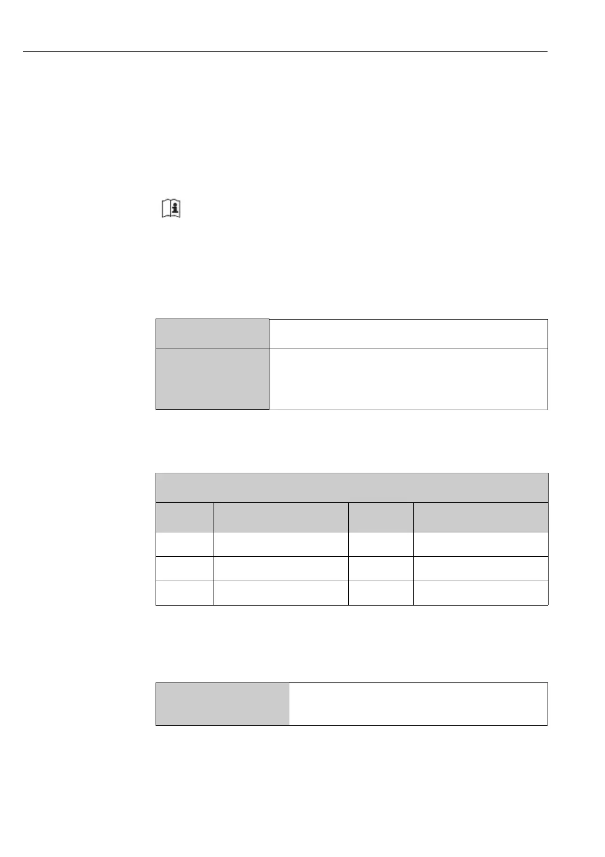
Max. entries
16 device parameters
Supported device
parameters
Only parameters with the following characteristics are sup-
ported:
• Access type: read or write access
• Data type: float or integer
Scan List
No. Modbus RS485 register Data type Configuration register
0 Scan list register 0 Integer Scan list register 0
. . . . . . Integer
15 Scan list register 15 Integer Scan list register 15
Master access to
data area
Via register addressses 5051 to 5081

 Loading...


