SC-F2000 Revision C
DISASSEMBLY & ASSEMBLY Disassembly and Assembly Procedure 171
Confidential
3.4.6.4 TRAY BOTTOM FRAME ASSY
1. Remove the FIXING LEVER. (p167)
2. Remove the PLATEN. (p71)
3. Remove the PARALLEL ADJUSTMENT PLATE. (p168)
4. Remove the PG SWITCH LEVER ASSY. (p169)
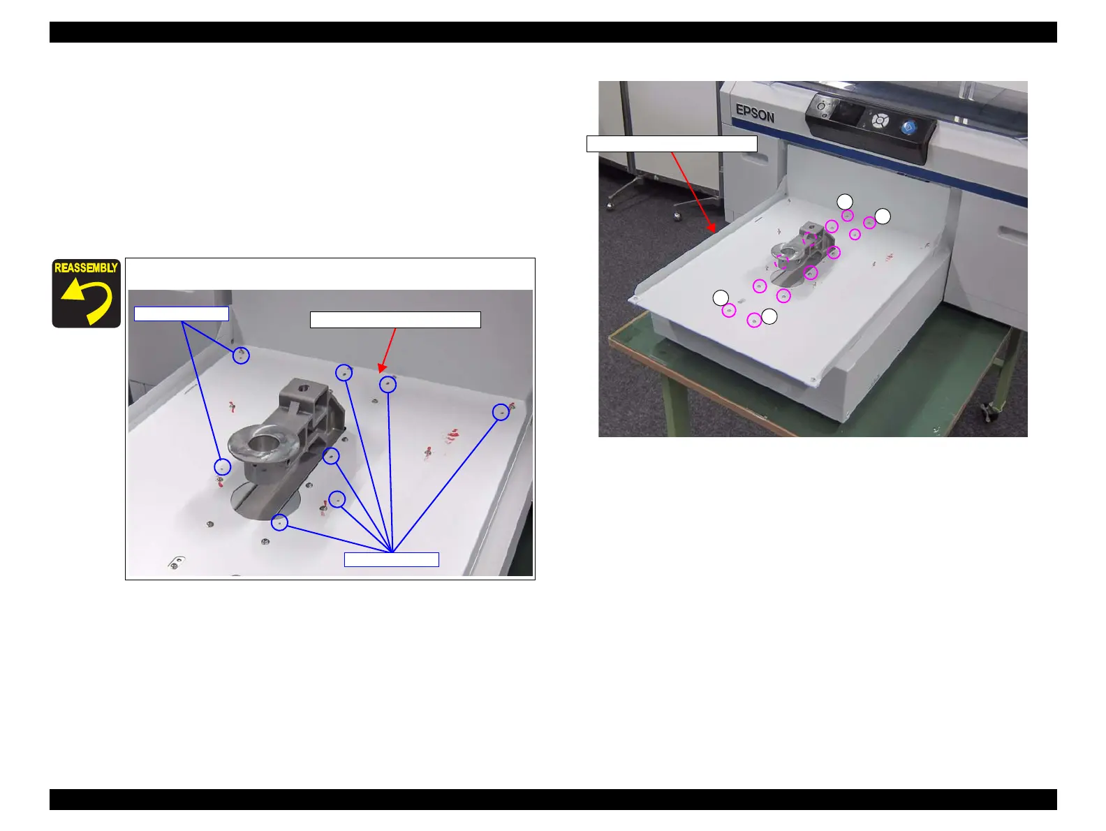
5. Remove the twelve screws that secure the TRAY BOTTOM FRAME ASSY.
A) Silver M3x6 Cup S-tite screw: 12 pcs
Figure 3-133. Removing the TRAY BOTTOM FRAME ASSY (1)
Pay attention to the eight positioning points.
Positioning points
TRAY BOTTOM FRAME ASSY
Positioning points
A
A
A
A
TRAY BOTTOM FRAME ASSY
 Loading...


