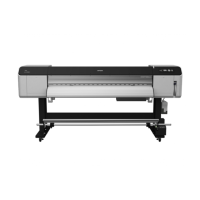
Epson Stylus Pro GS6000 Revision F
OPERATING PRINCIPLES Boards 46
Confidential
2.6 Boards
Figure 2-5. Boards
Diagram Name Description
1 Main Board Assembly
Communicates with the computer.
Processes received data.
Controls the printer mechanism.
Stores the correction values and various counters.
Generates the voltages for the logic system from the
voltage of 42V supplied from the P/S Board
Assembly.
2 Sub-A Board Assembly
Relays the connection between the Main Board
Assembly and the following parts.
CR Encoder
P Edge Sensor
PG HP Sensor
Print Heads
Cooling Fans
Diagram Name Description
3 Sub-B Board Assembly
Relays the connection between the Main Board
Assembly, P/S Term Board Assembly, Heater Cont
Board Assembly, Sub-C Board Assembly, and the
following parts.
IC Cover Sensor (right)
F Cover Sensor (right)
M Cover Sensor (right)
Sub Tank Sensors (right)
Pump Motors
Lever Sensor
Paper Rear Sensor
CR HP Sensor
4 Sub-C Board Assembly
Relays the connection between the Main Board
Assembly, P/S Term Board Assembly, Sub-B Board
Assembly and the following parts.
IC Cover Sensor (left)
F Cover Sensor (left)
M Cover Sensor (left)
Sub Tank Sensors (left)
PF Encoder
5 Sub-D Board Assemblies
Relay the connection between the Main Board
Assembly and the following parts.
Ink Cartridges (CSIC)
6
Heater Relay Board
Assembly
The assembly mounting the relays to control the
heaters.
7
Heater Cont Board
Assembly
Controls the heaters.
8
P/S Term Board
Assembly
Interface between the Main Board and the printer.
9 P/S Board Assembly
Generates the voltage for this printer from the AC
power supply.

 Loading...


