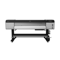
Epson Stylus Pro GS6000 Revision F
DISASSEMBLY & ASSEMBLY Disassembly and Assembly Procedure 85
Confidential
4.4.3 Housing
4.4.3.1 TOP COVER
1. Remove the two screws on the rear.
A) Silver, Phillips, Pan with S.W & P.W M4x8: two pieces
2. Slide the TOP COVER to the rear and remove it.
Figure 4-15. Removing the TOP COVER
Basically you can remove this part on the left and the one on the
right in the same way. Therefore this section describes the way to
remove the one on the right only.
When attaching the TOP COVER (right), make sure to set the
front left of it under the ALARM LED COVER. See Figure 4-15.
TOP COVER (right)
A
A
ALARM LED
A
As seen from the rear
When installing the TOP COVER, make sure to engage the hooks
on both sides to their positioning holes.
1
2
TOP COVER (inside)
Hook
Positioning hole
Inside

 Loading...


