5-48
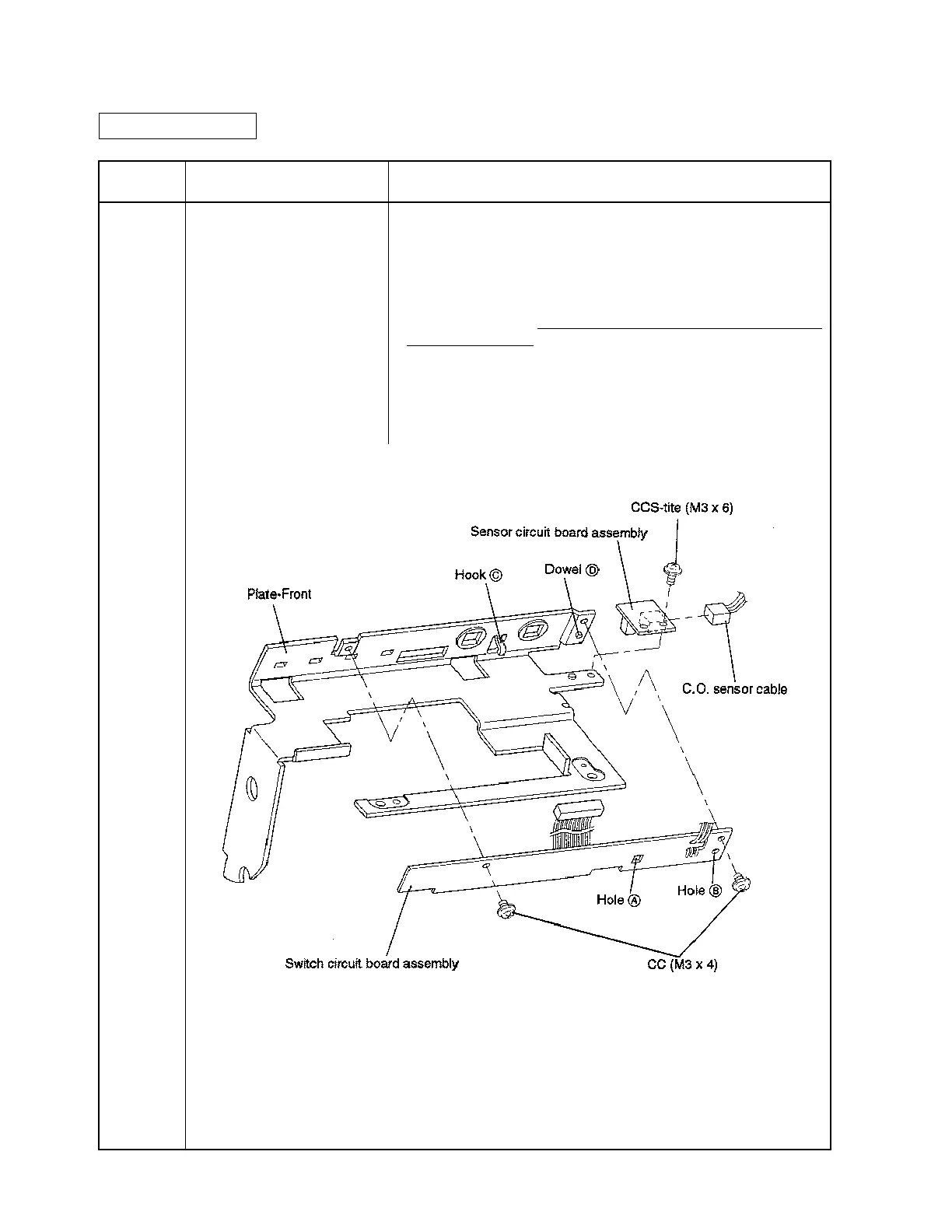
Sub-assembly F Switch Circuit Board Assembly and Sensor Circuit Board Assembly
Attachment
Assembly
Step
Part Name Assembly Procedure
1
2
3
★
Plate-Front
Switch circuit board assembly
CC (M3 x 4) x 2
Sensor circuit board assembly
CCS-tite (M3 x 6) x 1
• Align holes A and B in the Switch circuit board assembly with hook
C and dowel D on the Plate-Front, respectively; then fasten the board
assembly with the screws.
• Connect the C.O. sensor cable to the Sensor circuit board assem-
bly.
• Attach the Sensor circuit board assembly to the Plate-Front and
tighten the screw.
Be careful not to damage the sensor when
tightening the screw.
<Checkpoint>
• Make sure to align the dowel holes in the Switch circuit board
assembly and in the Sensor circuit board assembly with the
corresponding dowels on the Plate-Front.
CONFIDENTIAL

 Loading...


