1-10
■ Interface connector
Refer to Section 1.3.4,
Interface
.
■ Power supply connector
This connector is for the AC adapter.
Connector type:
TCS7960-532010 (Hosiden) or equivalent
TCP8927-631100 (Hosiden) or equivalent
TCP8927-531100 (Hosiden) or equivalent
Table 1-4. Power Supply Connector Pin Assignments
Pin Number Function
1 + 24 V DC
2 Signal ground
3NC
Shell Frame ground (FG)
Note
Be sure to ground the printer via the FG terminal on the
metal strip on the rear panel.
■ Drawer kick-out connector
(modular connector)
The pulse specified by the
ESC p command is output to this
connector. The host can confirm the status of the input
signal by using the DLE EOT, ESC u, GS a, or
GS r
commands.
Table 1-5. Drawer Kick-out
Connector Pin Assignments
Pin Number Signal Name I/O
1 Frame ground —
2 Drawer kick-out drive signal 1 (✽1) O
3 Drawer open/close signal (✽2) I
4 + 24 V DC —
5 Drawer kick-out drive signal 2 (✽1) O
6 Signal ground —
(✽1) Drawer kick-out drive signal
The signal specified by the ESC p command is output from
pins 2 and 5 of the connector.
Output voltage: approx. 24 V
Output current: 1 A max.
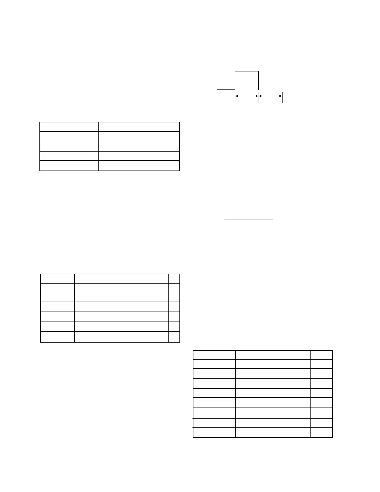
Output waveform (at connector pins 2 and 5):
(The ON time
n1
and OFF time
n2
are
determined by the ESC p command.)
≤ 0.2
Figure 1-16. Drawer Kick-out Drive Signal Timing
(✽2) Drawer open/close signal
The host computer can check the drawer open/close status
with the ESC u command.
Input signal level (at connector pin 3):
Low = 0 to 0.8 V
High = 2 to 5 V
Notes
• Use a shielded cable for the drawer connection.
• It is not possible to drive two drawers at the same time.
• The energizing duty of the drawer should be as follows:
On time
On time + Off time
• Use a solenoid rated for at least 24 Ω as the drawer kick-
out solenoid. Otherwise, excessive current may damage
the solenoid.
• The drawer must be powered from the printer (connector
pin 4).
• Never connect a telecommunication network to this
connector.
■ Customer display (DM-D) connector (modular
connector) [Not available for the TM-U375P]
This connector is used for the Epson customer display
(DM-D series). Never connect any other customer
displays.For the DM-D series, refer to the customer display
product specifications published by Epson.
Table 1-6. Customer Display Connector Pin Assign-
ment
Pin Number Signal Name I/O
1NC —
2NC —
3 TXD O
4 DTR O
5 DSR I
6 Signal ground —
7 +24 V DC —
8 Power ground —
Note
Never connect a telecommunication network or drawer
kick-out connector to this connector.
n1
x 2 ms
n2
x 2 ms
CONFIDENTIAL

 Loading...


