5-5
5.3 PRINTER MECHANISM
UNIT ASSEMBLY
The assembly process is divided into sub-assembly and
main assembly.
Perform the sub-assembly first to construct each unit from
the component parts. Then proceed to the main assembly.
When assembling the printer, check each part and its
attachment position by referring to Section 6.3,
Overall
Exploded Diagrams
.
A circled number in the
Assembly Step
column indicates
lubrication. Lubricants should be applied when assembling
the parts, since it is difficult to do so afterwards. Perform
lubrication by referring to Section 3.2.3,
Lubrication,
and to
Section 6.4,
General Lubrication Points Diagrams
.
A star (★) in the
Assembly Step
column indicates that
checking (<Checkpoint>) or adjustment (<Adjustment>) is
required. For adjustments, follow the descriptions in Sec-
tion 5.3.4,
Adjustments
. Whenever disassembly is per-
formed even for just one part, check whether adjustment is
necessary before reassembly.
An assembly step and part name enclosed in a parenthesis
indicate a part previously assembled or previously used
part that is being carried over into another assembly.
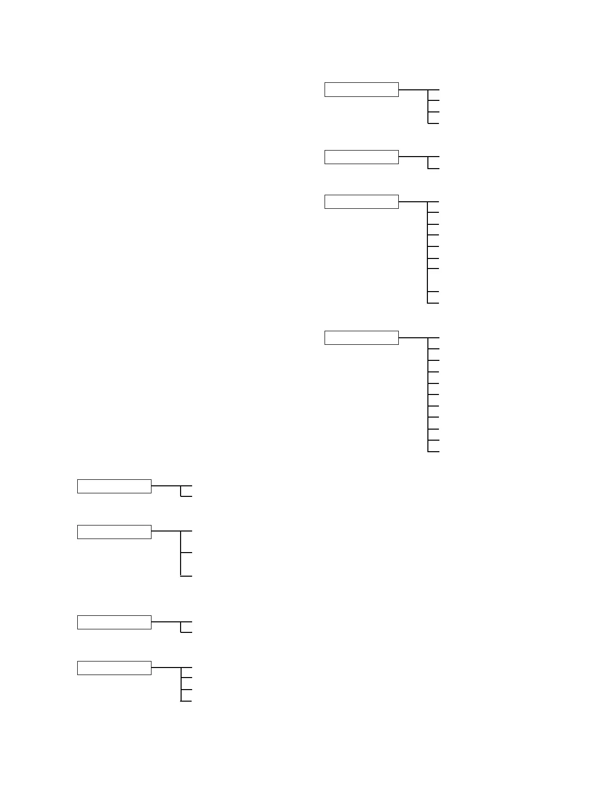
5.3.1 Component Parts
Component parts in each assembly are shown in the
following. Small parts such as screws are omitted.
FFC guide assembly
Sub-assembly A FFC-Print head
Guide-FFC
Relay circuit board assembly
Sub-assembly B Relay circuit board sub-
assembly
Carriage sensor sub-
assembly
Home position sensor
sub-assembly
Carriage assembly
Sub-assembly C Carriage sub-assembly
Belt
Paper holding lever assembly
Sub-assembly D Paper holding lever
Magnetic field block plate
Spring pin
S holding roller shaft
sub-assembly
Guide frame assembly B
Sub-assembly E J holding roller shaft
J holding roller
Guide frame sub-assembly
Spring-J holding roller
V sensor assembly
Sub-assembly F V sensor sub-assembly
Sensor holder
Platen holder unit
Sub-assembly G Platen
V movable lever spring
Plate-Platen mounting
Platen holder
Cover-Platen holder
Platen adjustment roller
Platen adjustment roller
holder
V movable lever
J feed roller shaft assembly
Ribbon frame assembly B
Sub-assembly H Frame-Ribbon
Microswitch sub-assembly
V holding roller shaft
Roller-Holding (small)
Roller-Holding (large)
Lever-J insertion
Spring-J insertion lever B
Guide-Slip paper
Lever-Ribbon frame
Spring-Ribbon frame
(Lead wires)
CONFIDENTIAL

 Loading...


