5-58
Assembly
Step
Assembly ProcedurePart Name
1
2
3
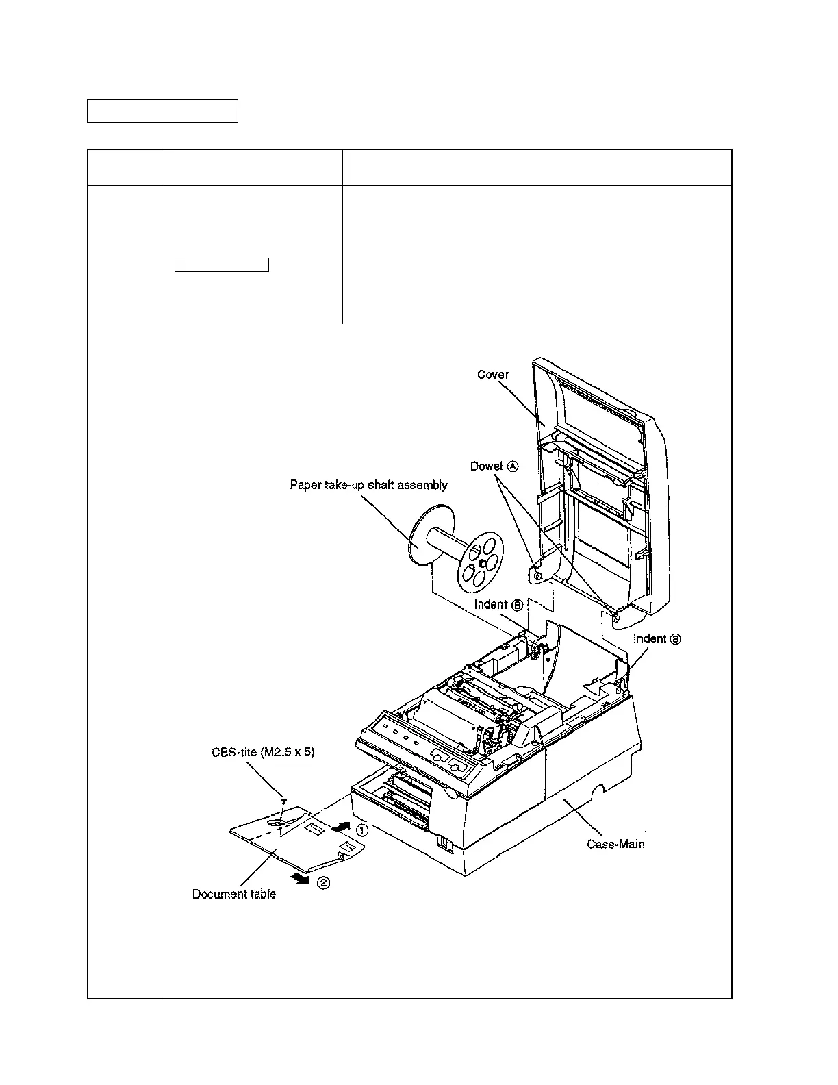
Document table
CBS-tite (M2.5 x 5) x 1
Cover
Sub-assembly B
Paper take-up shaft assembly
• Insert about the 2/3 (dotted line in the figure) of the Document table
into the Case-Main, as indicated by ➡ 1.
• Slide the table in the direction of ➡ 2, and secure it with the screw.
• Attach the Cover to the Case-Main by sliding dowels A onto indents
B.
• Attach the Paper take-up shaft assembly to the Case-main.
Main Assembly 10 Document Table, Cover, and Paper Take-up Shaft Assembly
Attachment
CONFIDENTIAL

 Loading...


