7-13
Whole Unit Main Assembly 1 Main Circuit Board Unit, Cables, and Cover-Circuit
Board
Assembly
Step
Part Name
1
2
3
4
5
6
7
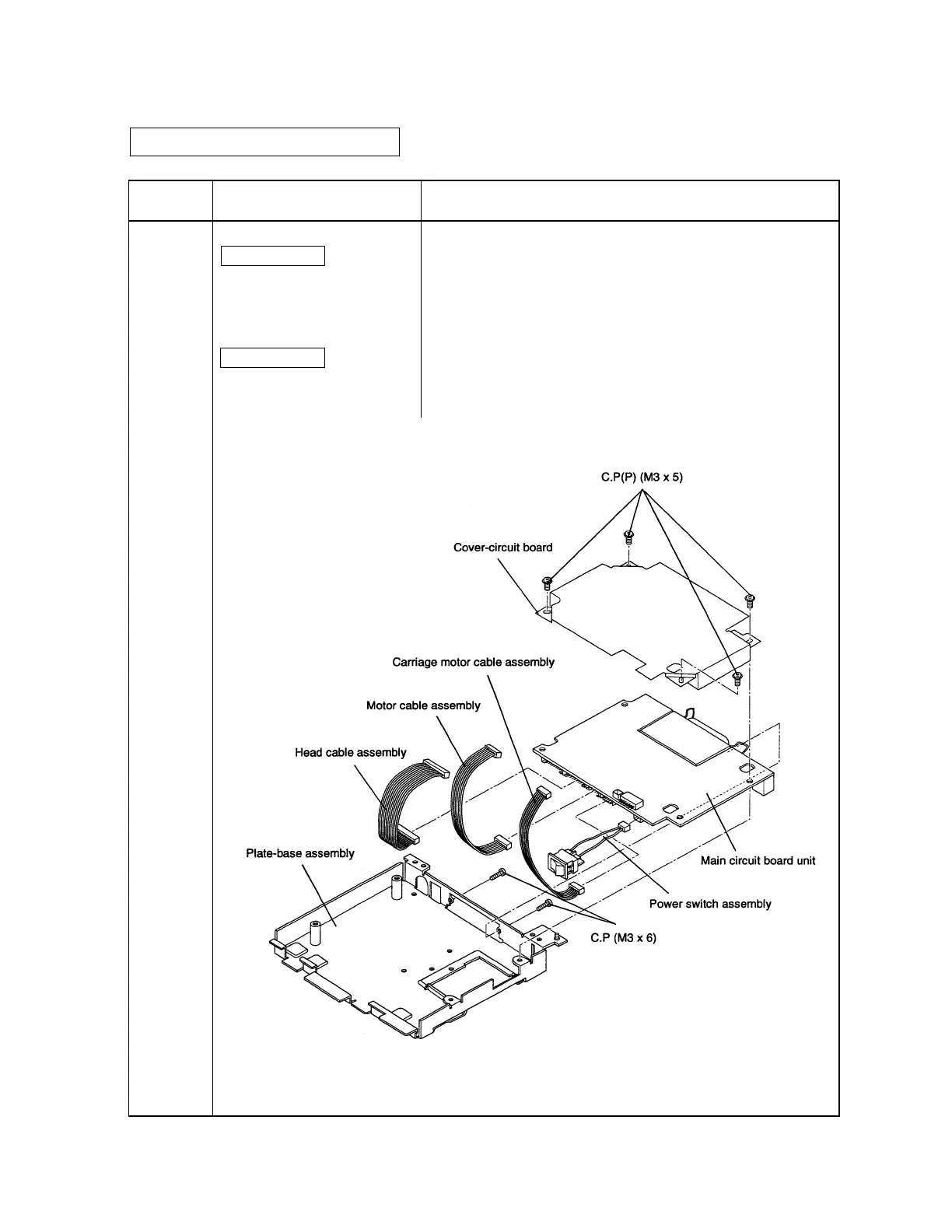
Main circuit board unit
Sub-assembly C
Motor cable assembly
Head cable assembly
Carriage motor cable assembly
Power switch assembly
Plate-base assembly
Sub-assembly E
Cover-circuit board
C.P(P) (M3 x 5) x 4
C.P (M3 x 5) x 2
• Attach the motor cable, head cable, carriage motor cable, and
power switch assemblies to the corresponding connectors on the
main circuit board unit.
• Place the main cicuit board unit on the plate-base assembly.
• Place the cover-circuit board on the main circuit board unit and
fasten the cover with the screws.
• Secure the screws to the plate-base assembly.
Assembly Procedure
CONFIDENTIAL

 Loading...


