5-4
Disassembly
Step
1
2
3
4
5
Disassembly Procedure
• Remove the Printer mechanism assembly from the Case-Main by performing
Main Assembly 5
to
10
in Section 5.4.3 in reverse.
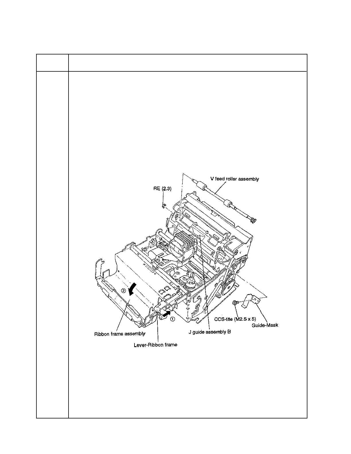
• Push the Lever-Ribbon frame in the ➡ 1 direction, and open the Ribbon frame assembly ( ➡ 2
direction).
• Remove the J guide assembly B and Guide-Mask fastening screw.
• Remove the V feed roller assembly fastening E-ring; then remove the roller assembly from the printer.
• Remove the J guide assembly B.
5.2.3 Removing the J Guide Assembly B (Cutter Blade)
CONFIDENTIAL

 Loading...


