2-2
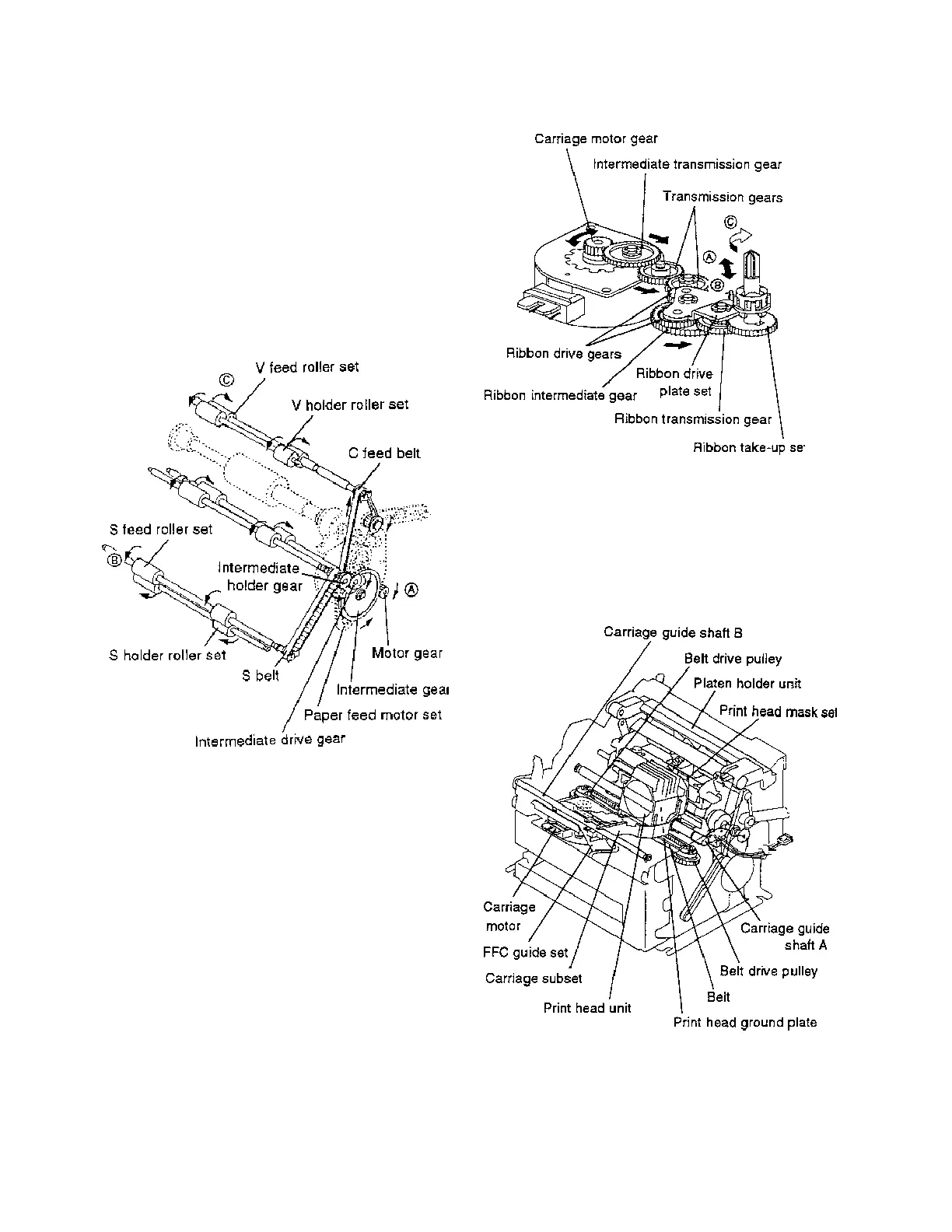
Figure 2-5. Ribbon Feed Gear Train
2.2.2 Printing Mechanism
The printing mechanism consists of the parts shown in
Figure 2-6, including a print head unit with nine wires in a
vertical row.
Figure 2-6. Printing Mechanism
Gear train for feeding slip paper
When the paper feed motor set drives the motor gear so
that it rotates in the direction of ➡ A, the intermediate gear
rotates in the direction of the ➡, and the intermediate drive
gear and intermediate holder gear rotate in sequence in the
direction of the ➡.
Note that because the C feed belt is connected to the
intermediate drive gear and the S belt is connected to the
intermediate holder gear, the S feed roller set rotates in the
direction of ➡ B and the V feed roller set rotates in the
direction of ➡ C by means of the respective belts.
Figure 2-4. Gear Train for Feeding Slip Paper
Ribbon feed gear train
The ribbon feed gear train consists of the parts shown in
Figure 2-5.
The ribbon drive plate set moves, using the ribbon interme-
diate gear shaft as a fulcrum, in either the direction of ➡ A
or ➡ B each time the carriage motor rotates forwards and
backwards. Only when the ribbon intermediate gear shaft
moves in the direction of ➡ A does the ribbon drive gear
mesh with the ribbon transmission gear so that the ribbon
take-up set rotates in the direction of ➡ C.
CONFIDENTIAL

 Loading...


