5-17
Sub-assembly I Print Frame Unit Assembly B
Assembly
Step
1
2
3
★
Assembly ProcedurePart Name
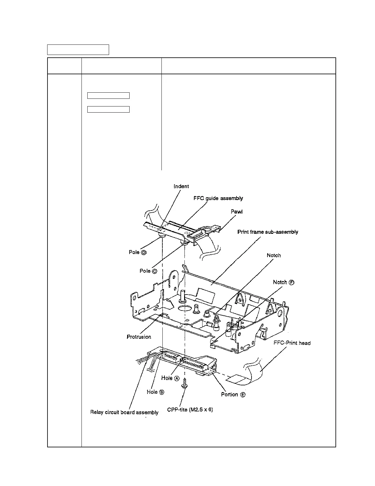
Print frame sub assembly
FFC guide assembly
Sub-assembly A
Relay circuit board assembly
Sub-assembly B
CCP-tite (M2.5 x 6) x 1
• Align the FFC guide ass'y pawl with the print frame sub-assembly
notch, and align the indent with the protrusion.
• Attach the FFC-Print head to the relay circuit board assembly connec-
tor.
• Align relay circuit board assembly holes A and B with FFC guide
assembly poles C and D, respectively, while engaging portion E in
notch F; then tighten the screw in hole A.
<Checkpoint>
• Verify that the FFC-Print head is fully inserted to the connector.
CONFIDENTIAL

 Loading...


