7800/7700 MultiFrame Manual
7814 Series Dual HDTV Up/Down/Cross Converters
Revision 1.1.3 Page - 13
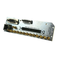
2.3. GPIO CONNECTOR
There are 8 General Purpose Inputs/Outputs (GPIOs) on the 7814 series modules. Each GPIO may be
configured to be an input or configured to be an output. These GPIOs are interfaced using a 15-pin DB
connector and an associated breakout cable (cable part # WPAES8-DINM-9W-6F). NOTE: The GPIO
breakout cable is not included with the module when purchased. Table 2-1 shows the Pin-out of this
connector is as follows:
Name Description Colour
General Purpose Input /Output #1
2
External LTC Out
General Purpose Input /Output #2
General Purpose Input /Output #4
5
External 6 Hz In
General Purpose Input /Output #3
General Purpose Input /Output #8
General Purpose Input /Output #5
General Purpose Input /Output #6
General Purpose Input /Output #7
Table 2-1: GPIO Connector Pin out