7800/7700 MultiFrame Manual
7814 Series Dual HDTV Up/Down/Cross Converters
Page - 14 Revision 1.1.3
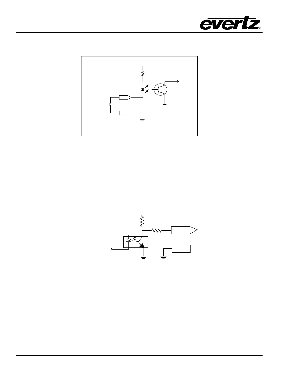
When a particular GPIO is configured to be a GPI, the following interface shall apply:
GPI
GND
GPI
Command
to
internal
circuit
3.6 K
+ 5
VDC
Figure 2-5: GPI Input Circuitry
When a particular GPIO is configured to be a GPO, the interface shown below shall apply. The GPO is
active low with internal pull up (10k Ohm) resistors to +5V. When the output goes low, it is able to sink up
to 10mA. When high, the signal will go high (+5V). Do not draw more than 100
µA from the output.
Figure 2-6 shows the circuit for the general-purpose output.
From Internal
Circuit
+ 5 Volts
GND
GPO
10 ohm
10 K
Figure 2-6: GPO Output Circuitry