153
ELECTRICAL AND IGNITION
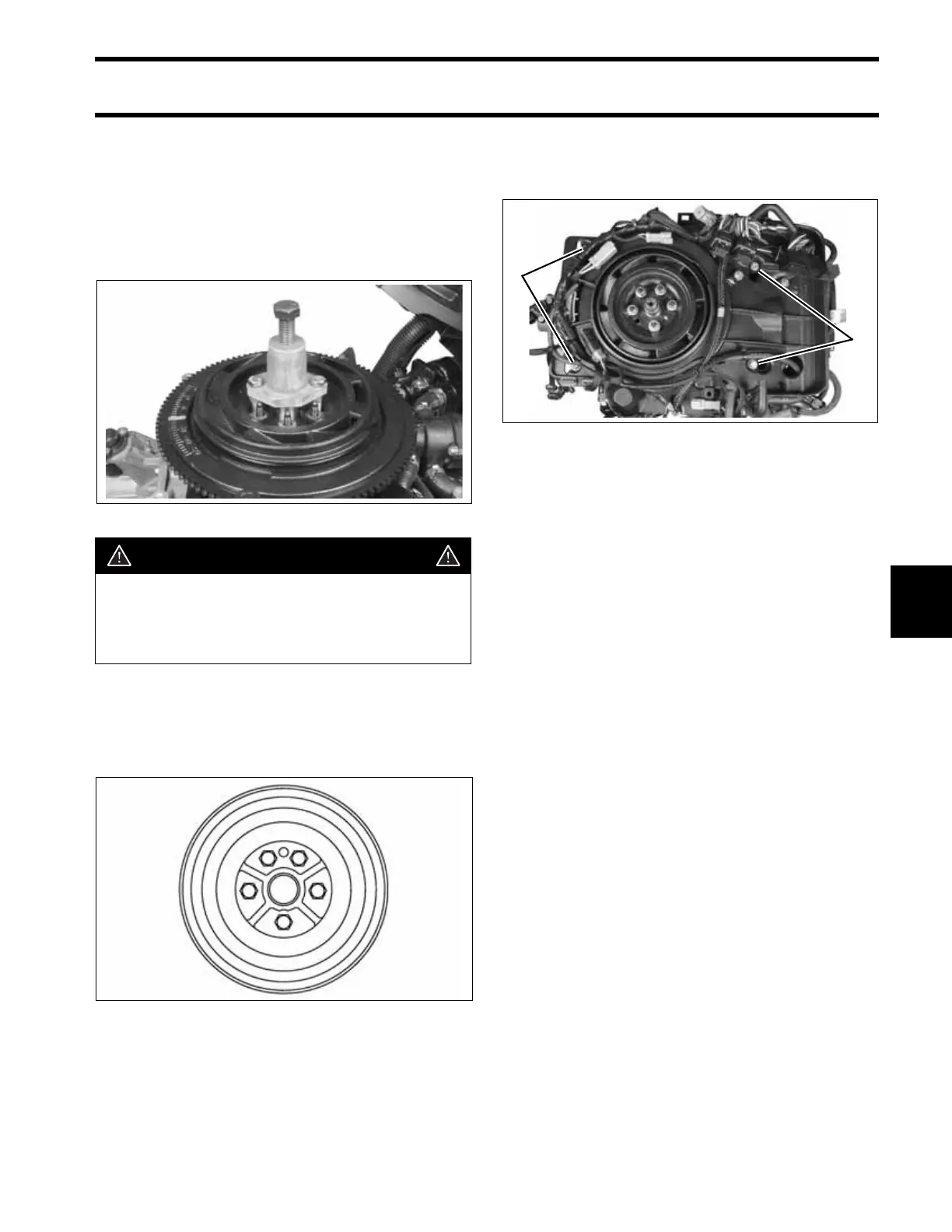
FLYWHEEL AND STATOR SERVICING
7
Use Flywheel Puller Adaptor Kit, P/N 5007181,
and Flywheel Service Kit, P/N 434649, to position
flywheel on top of crankshaft. Align the alignment
hole in flywheel with alignment pin of crankshaft.
Turm center screw counterclockwise to lower fly-
wheel onto crankshaft. Remove tools from the fly-
wheel and crankshaft.
Apply Triple-Guard grease to studs and install five
new flywheel retaining nuts and washers. Follow
torque sequence below. Tighten nuts to a rorque
of 24 to 26 ft. lbs. (32.5 to 35 N·m).
Install the electrical harness base and secure with
four screws. Tighten screws to a torque of 60 to
84 in. lbs (7 to 9.5 N·m).
Reconnect the stator connector, two port side trim
system connectors, port engine temperature sen-
sor, and the port ground terminal.
Reconnect the crankshaft position sensor, throttle
position sensor, air temperature sensor, and oil
pump electrical connectors.
Install the EMM. Refer to EMM SERVICING on
p. 110.
IMPORTANT: Check ignition timing after fly-
wheel removal or replacement. Refer to TIMING
ADJUSTMENTS on p. 154.
005383
CAUTION
To avoid damage to flywheel magnets, or
injury to fingers, Flywheel service kits,
P/N 434649 and P/N 5007181, must be
used to remove or install the flywheel.
Flywheel Torque Sequence DRC3737
2 5
4
1
3
1. Harness base screws 005378
1
1