192
FUEL SYSTEM
FUEL COMPONENT SERVICING
Place gasket on throttle body. Install throttle body,
with oil pump bracket on reed plate and install
screws.
Tighten the center screws first and expand out-
ward. Final torque is 96 to 120 in. lbs. (11 to 13.5
N·m).
Tighten small oil pump bracket screw 24 to 36 in.
lbs. (3 to 4 N·m).
Install oil pump in bracket and secure with Oetiker
clamp. Route oil distribution hoses through reed
plate bracket and install in oil pump manifold.
Refer to OIL SUPPLY DIAGRAMS – V4 on p. 196
or OIL SUPPLY DIAGRAMS – V6 on p. 198.
Install oil filter and oil and fuel supply hoses.
Install crankshaft position sensor.
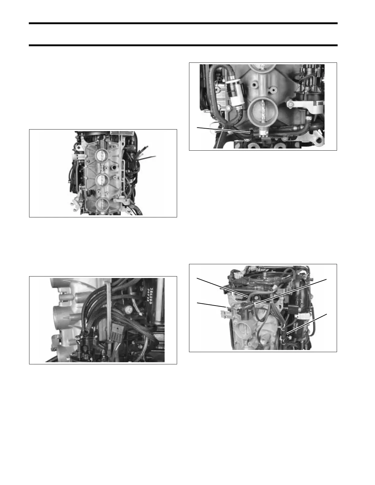
Install vapor separator vent hose and oil recircula-
tion hose. Secure with tie straps.
Connect throttle linkage and throttle position sen-
sor connector.
Secure connector to reed plate bracket with tie
strap.
IMPORTANT: DO NOT lubricate throttle link-
ages.
Refer to TPS CALIBRATION on p. 156.
005362
005344
1. Tie strap 005343
1. Vapor separator vent hose
2. Throttle linkage
3. TPS electrical connector
4. Tie strap
005361
1
3
4
1
2