252
POWERHEAD
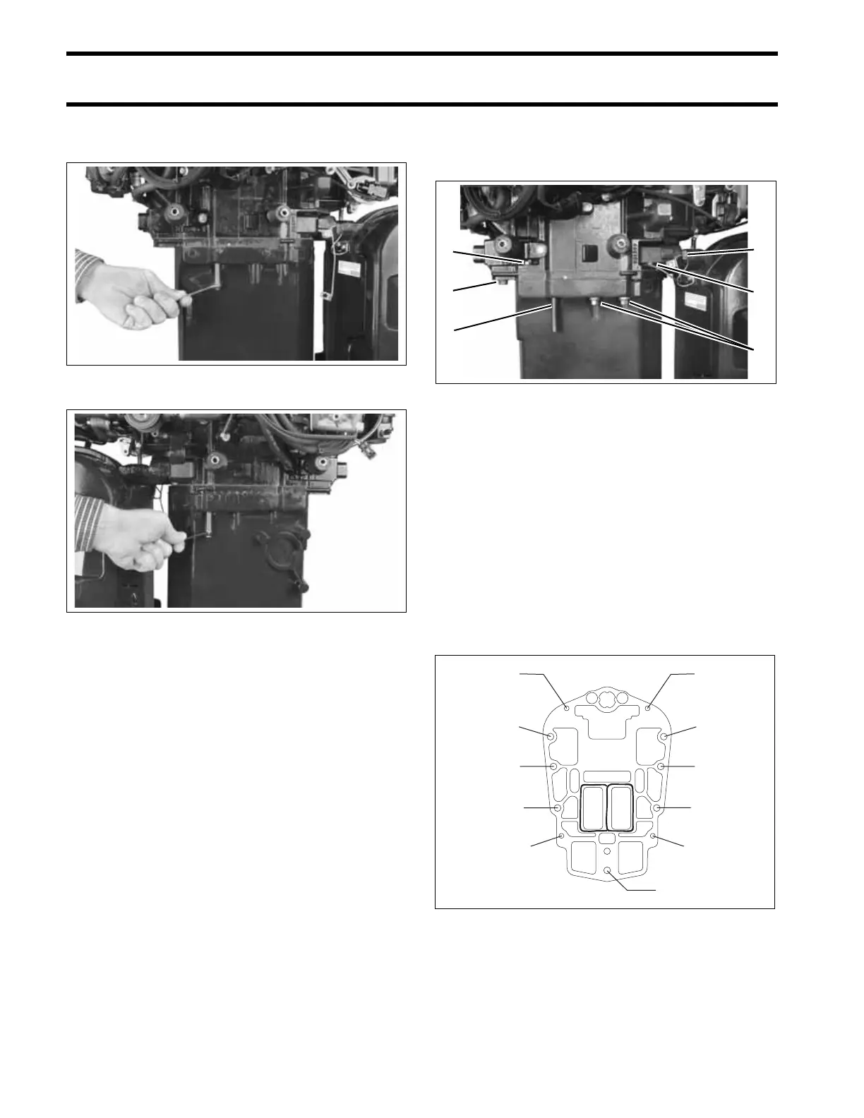
POWERHEAD INSTALLATION
Install pins from Alignment Pin Kit, P/N 5007167,
as shown. Tighten pins until fully seated.
Apply Triple-Guard grease to the threads, and
Gasket Sealing Compound to the shank of the
powerhead screws.
Apply Triple-Guard grease to upper mount screw
threads.
With alignment pins in place, loosely install
remaining powerhead screws and upper mount
screws.
• Tighten the large powerhead screws, 1 through
4, to a torque of 20 to 22 ft. lbs (27 to 30 N·m).
• Remove Alignment Pins and tighten screws 5
through 7 to a torque of 20 to 22 ft. lbs (27 to 30
N·m).
• Ttighen the four small powerhead screws to a
torque of 60 to 84 in. lbs. (7 to 9.5 N·m).
• Tighten the upper mount screws to a torque of
110 to 130 ft. lbs. (149 to 176 N·m). Make sure
that screw heads are tight against steering arm.
IMPORTANT: Retighten powerhead mounting
screws after outboard has been run at full operat-
ing temperature and allowed to cool.
005274
005275
1. Large powerhead screws
2. Small powerhead screws
3. Upper mount screws
4. Alignment pin tool
005277
Large screw torque sequence, 1–7
Small screw torque sequence, A–D
005244
3
2
1
2
1
4
1
2
3
4
5
6
7
Alignment
Pin here
A
B
CD
Alignment
Pin here