303
GEARCASE
GEARCASE REMOVAL AND INSTALLATION
13
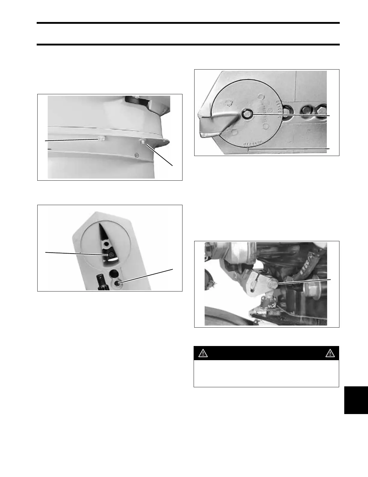
Apply Gasket Sealing Compound to threads of the
gearcase retaining screws. Tighten the screws to
a torque of:
• 3/8 in. screws – 26 to 28 ft. lbs. (35 to 38 N·m)
• 7/16 in. screws – 40 to 50 ft. lbs. (54 to 68 N·m)
Apply Gasket Sealing Compound to threads of the
trim tab screw. Install gasket on “M”-type gear-
cases. Install and align the trim tab (cover on “L”-
type) with the index marks noted prior to disas-
sembly. Tighten the trim tab screw to a torque of
35 to 40 ft. lbs. (47 to 54 N·m). For adjustment,
refer to Trim Tab Adjustment on p. 70.
IMPORTANT: Standard rotation and counter
rotation trim tabs must not be interchanged. This
would result in inadequate cooling water supply to
the propeller hub.
Place the shift rod in the shift rod lever. Install the
retaining pin and washer. Tighten pin to a torque
of 60 to 84 in. lbs. (7 to 9.5 N·m).
IMPORTANT: During break-in period of a reas-
sembled gearcase, change the gearcase lubricant
between 10 to 20 hours of operation.
1. Alignment screw
2. 3/8 in. screw
005403
1. 7/16 in. screw
2. 3/8 in screw
COA3139
1
2
1
2
1. Trim tab screw
2. Index mark
COA3663
1. Shift rod screw 004241
WARNING
To prevent loss of operator control, check
for proper shifting operation and adjust, if
necessary.
1
2
1