Testing Fibers
78 OX1
Working With Link View
Working With Link View
This graphic representation displays, one at a time, all of its faults (Fault
Xplorer), or all of its detectable elements (Link Mapper), present on the
link from the first connector to the last element detected. You have to use
the navigation arrows to see each element.
When you select an element in the link view, it is automatically selected in
the link overview as long as it is located within the link start and the link
end. See Working With Link Overview on page 77 for details.
Note: The link view is not available in Flash Advisor.
The application assigns a sequential number to each element or fault
displayed along the link between the link start (A) and the link end (B).
Only one identification number is assigned for a group of elements.
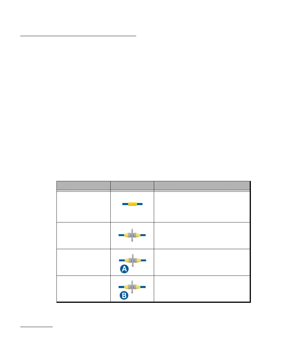
The elements are represented by the following icons:
Element Name Element Icon Meaning
Splice The splice can indicate the junction
of two fiber sections, or any
non-reflective loss induced by a
bend or coupler, for instance.
Connector The connector is used to join two
fibers.
Connector A Connector A corresponds to the link
start.
Connector B Connector B corresponds to the link
end.
 Loading...