SMP 300 Series • Remote Communication and Control 107
Ethernet (LAN) Port
The rear panel LAN connector (see figure4,
Q
on page15) on the device can be
connected to an Ethernet LAN or WAN. Communication between the device and the control
system or PC is via Telnet (a TCP socket using port 23). The Telnet port can be changed, if
necessary, via SIS or using the SMP300 Series web UI. This connection makes SIS control
of the device possible using a control system or PC connected to the same LAN or WAN.
LAN port defaults:
• DHCP:
off
• SMP300 Series IP address:
192.168.254.254
• Subnet mask:
255.255.0.0
• Gateway IP address:
0.0.0.0
Ethernet Connection
The Ethernet cable can be terminated as a straight‑through cable or a crossover cable and
must be properly terminated for your application.
• Crossover cable — Direct connection between the computer and the SMP.
• Patch (straight) cable — Connection of the SMP to an Ethernet LAN.
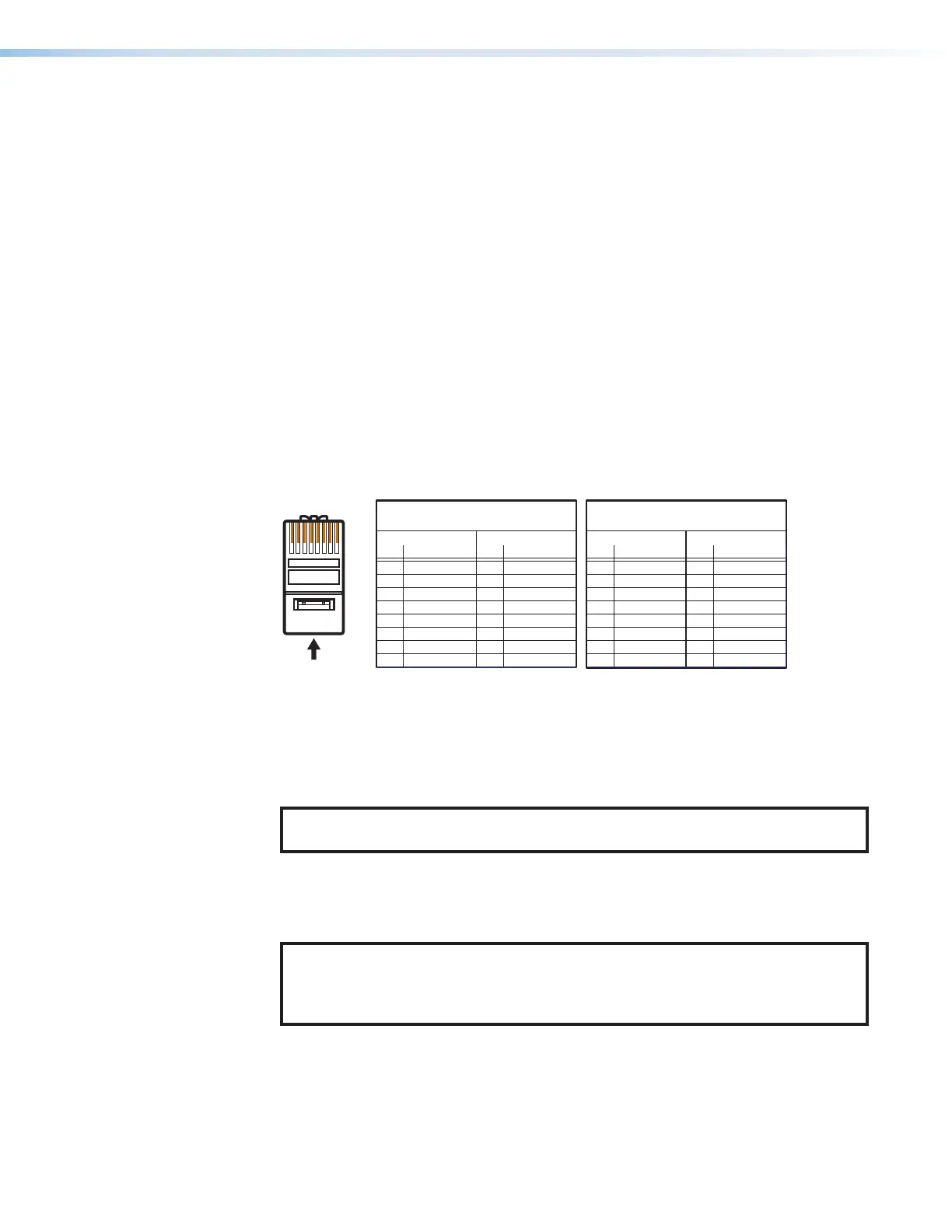
12345678
RJ-45
Connector
Insert Twisted
Pair Wires
Pins:
A cable that is wired as TIA/EIA T568A at one
end and T568B at the other (Tx and Rx pairs
reversed) is a "crossover" cable.
A cable wired the same at both ends is called
a "straight-through" cable because no pin/pair
assignments are swapped.
T568B T568A T568B T568B
Straight-through Cable
(for connection to a switch, hub, or router)
End 1 End 2
Pin Wire Color Pin Wire Color
1 white-orange 1 white-orange
2 orange 2 orange
3 white-green 3 white-green
4 blue 4 blue
5 white-blue 5 white-blue
6 green 6 green
7 white-brown 7 white-brown
8 brown 8 brown
Crossover Cable
(for direct connection to a PC)
End 1 End 2
Pin Wire Color Pin Wire Color
1 white-orange 1 white-green
2 orange 2 green
3 white-green 3 white-orange
4 blue 4 blue
5 white-blue 5 white-blue
6 green 6 orange
7 white-brown 7 white-brown
8 brown 8 brown
Figure 93. RJ-45 Ethernet Connector Pin Assignments
To establish a network connection to the SMP:
1. Open a TCP socket to port 23 using the SMP 300 Series IP address.
NOTE: If the local system administrators have not changed the value, the
factory‑specified default, 192.168.254.254, is the correct value for this field.
2. The SMP responds with a copyright message including the name of the product,
firmware version, part number, and the current date and time.
3. The device is password protected, enter the appropriate name, admin or user and
password.
NOTE: The factory configured passwords for all accounts on this device have
been set to the device serial number. In the event of a complete system reset, the
passwords convert to the default, which is no password (see Users and Roles
on page86 to change a password).
a. If the password is accepted, the device responds with Login User or Login
Administrator.
b. If the password is not accepted, the Password prompt returns.
93