SMP 300 Series • Installation 17
Input Connections
The audio and video inputs are grouped into channel A and channel B (see figure4 on
page15).
• Channel A analog audio input can be selected for video inputs 1 or 2 (
F
).
• Channel B analog audio can be selected for video inputs 3 (
H
), 4 (
I
), or 5 (
J
).
F
HDMI input (1 and 2) — Connect an HDMI (or DVI with suitable adapter) source device
to input 1 and input 2.
NOTE: Channel A (inputs 1 and 2) is optimized for full range sources such as PCs.
When using a video source with adjustable quantization range on these inputs,
select "Full Range" for the most accurate video reproduction.
G
Channel A analog audio input — Connect a balanced or unbalanced stereo line
level audio device to this 5-pole, 3.5 mm captive screw port. Channel A audio can be
selected for output with HDMI inputs 1 and 2 instead of the embedded audio. Wire the
connector as shown in figure5.
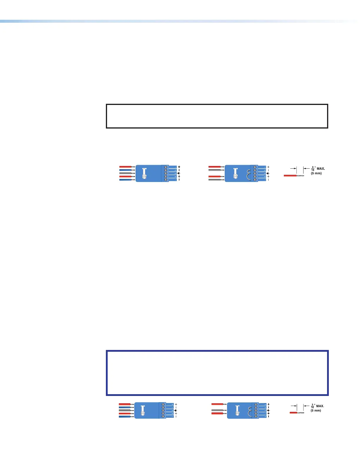
Unbalanced Stereo InputBalanced Stereo Input
(high impedance)(high impedance)
Do not tin the wires!
Tip
Sleeve
Sleeve
Tip
Left
Right
Tip
ve(s)
Ring
Ring
Tip
Left
Right
Figure 5. Audio Input Captive Screw Connector Wiring
H
Analog video input 3 — Connect component video to the three BNC connectors (B-Y,
R-Y, VID/Y). Connect a composite video signal to the VID/Y BNC connector.
I
HDMI input 4 — Connect an HDMI (or DVI with suitable adapter) source device to
input4.
J
Serial digital video input 5 (SMP 351 3G-SDI and SMP 352 3G-SDI only) —
Connect a 3G/HD/SDI video signal to this BNC connector.
K
Channel B analog and 3G-SDI audio input — Connect a balanced or unbalanced
stereo line level audio device to this 5-pole, 3.5mm captive screw port. ChannelB
audio can be selected from either the HDMI embedded audio, ChB analog audio, or
the audio can be set to Off. Wire the connector as shown in figure5.
Output Connections
L
HDMI loop-thru output — Connect an HDMI (or DVI with suitable adapter) display
device to the HDMI Loop Thru output to view the selected input 1 or input 2.
M
Audio loop output — Connect a balanced or unbalanced stereo line level audio device
to this 5-pole, 3.5 mm captive screw port. Wire the connector as shown in figure6.
Audio is always from audio input (
G
).
ATTENTION:
• For unbalanced audio, connect the sleeves to the ground contact. DO NOT
connect the sleeves to the negative (–) contacts.
• Pour l’audio asymétrique connectez les manchons au contact au sol. Ne PAS
connecter les manchons aux contacts négatifs (–).
Balanced Audio Output Unbalanced Audio Output
Do not tin the wires!
Tip
Ring
Ring
Tip
Left
Right
Left
Tip
Sleeve(s)
NO Ground Here
NO Ground Here
Tip
Right
Figure 6. Audio Output Captive Screw Connector Wiring
5
6