Programming manual
CNC 8055
CNC 8055i
PROBING
12.
·M· & ·EN· MODELS
SOFT: V02.2X
·321·
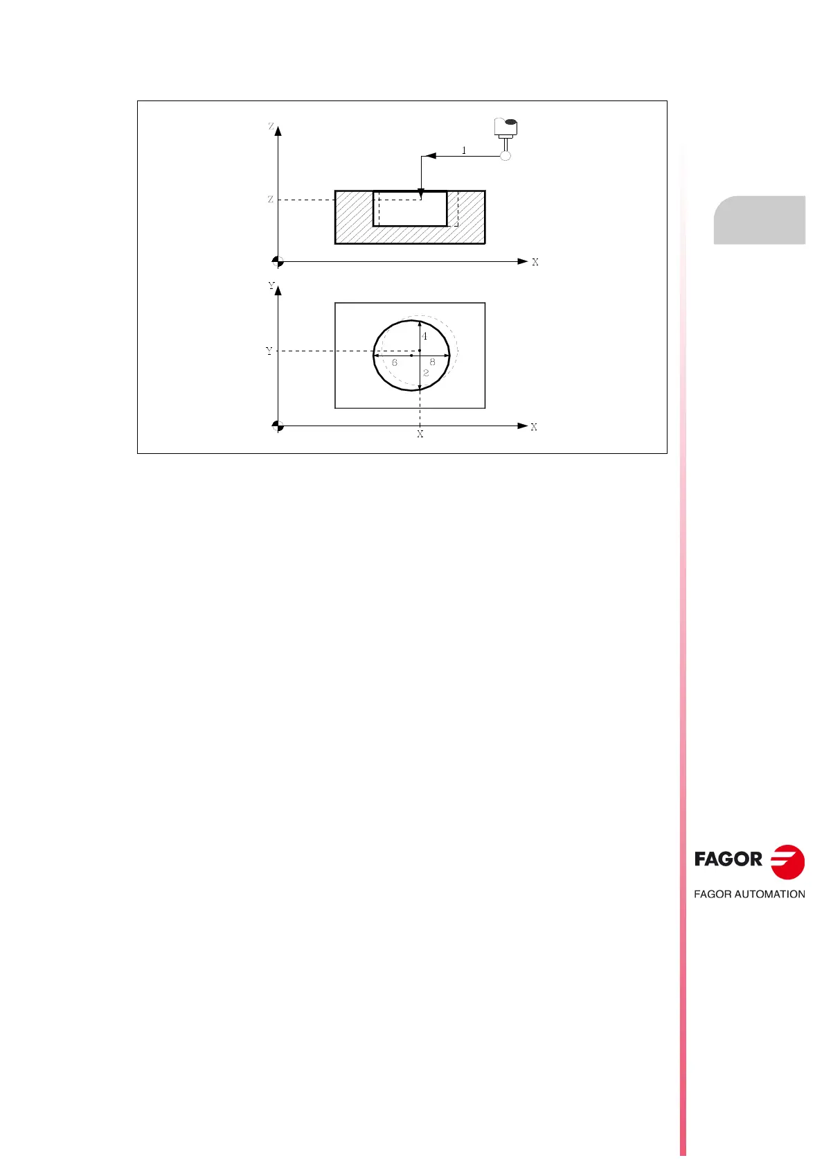
PROBE 8. Hole measuring cycle
12.10.1 Basic operation
1. Approach movement.
Probe's rapid movement (G00) from the cycle calling point to the center of the hole.
The approaching movement is made in two stages:
·1· Movement in the main work plane.
·2· Movement along the longitudinal axis.
2. Probing movement.
This movement consists of:
·1· Movement of the probe along the ordinate axis at the indicated feedrate (H), until the probe
signal is received.
The maximum distance to be traveled in the probing movement is "B+(J/2), if, after travelling
that distance, the CNC does not receive the probe signal, it will display the corresponding
error code and stop the movement of the axes.
·2· Return of the probe in rapid (G00) the distance indicated in (E).
·3· Movement of the probe along the abscissa axis at the indicated feedrate (F), until the probe
signal is received.
3. Withdrawal movement.
Movement of the probe in rapid (G00) from the point where it probed to the theoretical center
of the hole.
4. Second probing movement.
Same as above.
5. Withdrawal movement.
Movement of the probe in rapid (G00) from the point where it probed to the real center
(calculated) of the hole along the ordinate axis.
6. Third probing movement.
Same as above.
7. Withdrawal movement.
Movement of the probe in rapid (G00) from the point where it probed to the theoretical center
of the hole.
8. Fourth probing movement.
Same as above.
 Loading...


