Programming manual
CNC 8055
CNC 8055i
PATH CONTROL
6.
·M· & ·EN· MODELS
SOFT: V02.2X
·87·
Circular interpolation (G02, G03)
6.3 Circular interpolation (G02, G03)
There are two ways of carrying out circular interpolation:
G02: Clockwise circular interpolation.
G03: Counterclockwise circular interpolation.
Movements programmed after G02 and G03 are executed in the form of a circular path and at the
programmed feedrate "F".
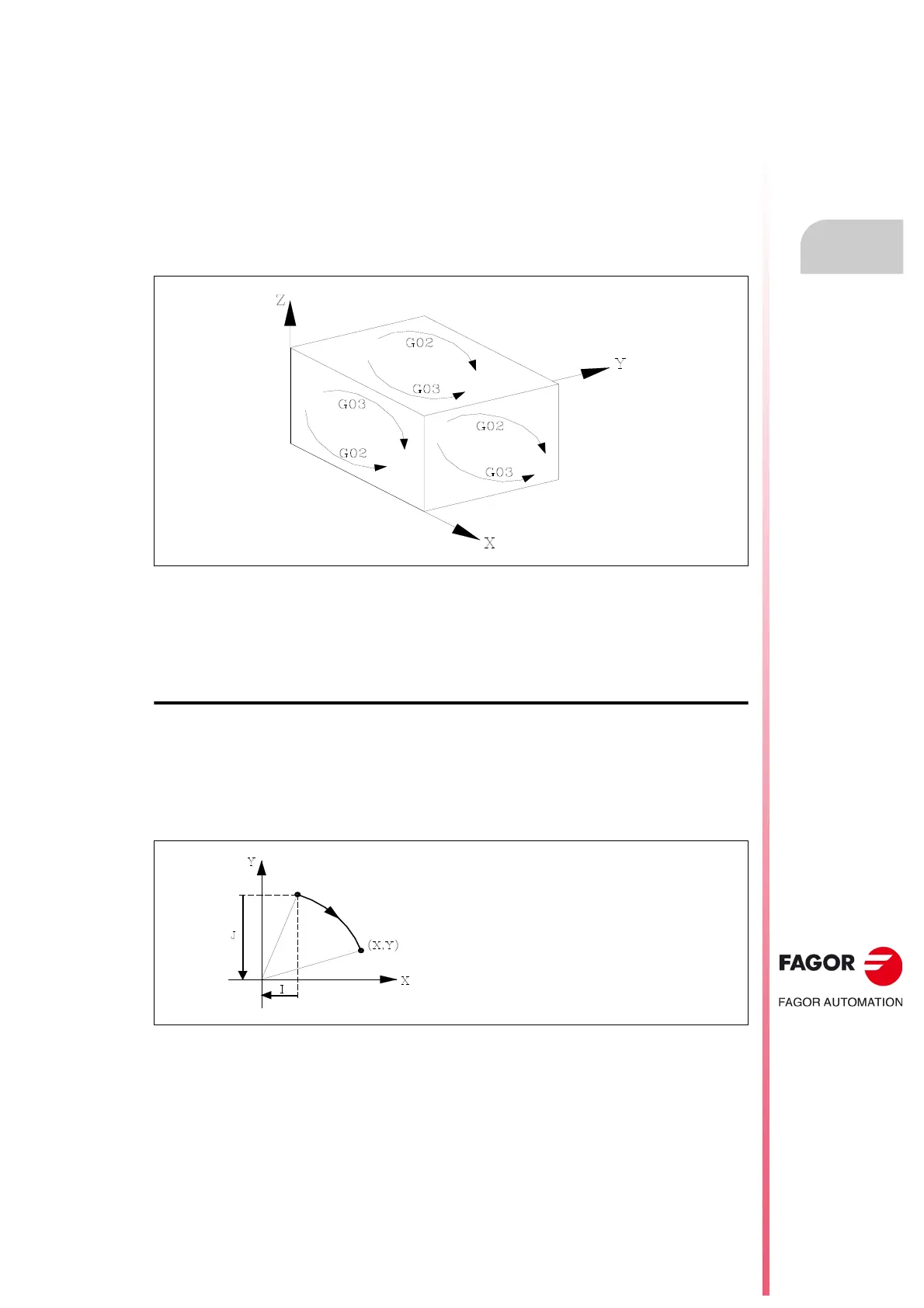
Clockwise (G02) and counterclockwise (G03) definitions are established according to the system
of coordinates shown below:
This system of coordinates refers to the movement of the tool on the part.
Circular interpolation can only be executed on a plane. The form of definition of circular interpolation
is as follows :
Cartesian coordinates
The coordinates of the endpoint of the arc and the position of the center with respect to the starting
point are defined according to the axes of the work plane.
The center coordinates are defined in radius by the letters I, J, or K, each one of these being
associated to the axes as follows: When not defining the center coordinates, the CNC assumes that
their value is zero.
Programming format:
Plane XY: G02(G03) X±5.5 Y±5.5 I±6.5 J±6.5
Plane ZX: G02(G03) X±5.5 Z±5.5 I±6.5 K±6.5
Plane YZ: G02(G03) Y±5.5 Z±5.5 J±6.5 K±6.5
Axes X, U, A ==> I
Axes Y, V, B ==> J
Axes Z, W, C ==> K