OBID i-scan
®
System-Manual ID ISC.MR/PR/PRH101
FEIG ELECTRONIC GmbH Page 25 of 131 H60301-3e-ID-B.doc
3.3. CFG2: Inputs / Outputs general
Via the following parameters the operation mode of the LED and the buzzer (only ID ISC.PRH101) can
be configured at any time. One byte each is reserved for the active and mute position, by means of
which the individual operation modes according to the schedule below may be adjusted. In addition to
this, for the active- and mute position different flashing frequencies of the LED and intervals of the
buzzer may be defined. So, the LED may be used as an operation indicator.
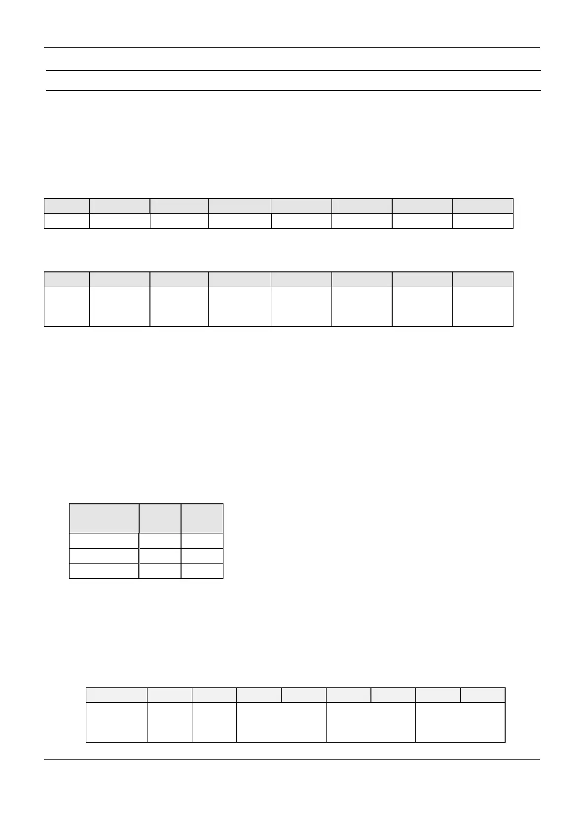
Byte 0 1 2 3 4 5 6
Contents 0x00 0x00 0x00 IDLE-STATE IDLE-FLASH 0x00 0x00
Default 0xA9 0x00
Byte 7 8 9 10 11 12 13
Contents ACTIV-
STATE
ACTIV-
FLASH
ACTIV-
GRN-TIME
ACTIV-
RED-TIME
ACTIV-
BUZZER-
TIME
0x00 0x00
Default MR/PR: 0x26
PRH: 0x96
0x00 0x0A 0x0A MR/PR: 0x00
PRH: 0x05
1 sec. 1 sec. 1 sec.
USB-Ver-
sion
MR/PR: 0x26
PRH: 0x96
MR/PR: 0x00
PRH: 0x05
Note:
• The Readers dispose of a two colored LED (red / green). The color orange can be obtained
by combining both basic colors red and green.
Colors ID ISCMR / PR:
LED
Color:
red green
red 1 0
green 0 1
orange 1 1
• The buzzer is only with the ID ISC.PRH101 available.
IDLE-STATE / ACTIVE-STATE
One byte each for idle- and tag-detect state is used to set the operation mode of the signal
transmitter.
Bit: 7 6 5 4 3 2 1 0
Function: Startup
Buzzer/
LED
0 BUZZER RED
(PRH: BLUE)
GRN
 Loading...