9 Measurement
9.3 Start of the measurement FLUXUS F60*
2017-10-16, UMFLUXUSF60xV5-0EN
104
Fine adjustment of the transducer distance
• If the displayed transducer distance is adjusted, press ENTER.
The measuring run for the positioning of the transducers is started.
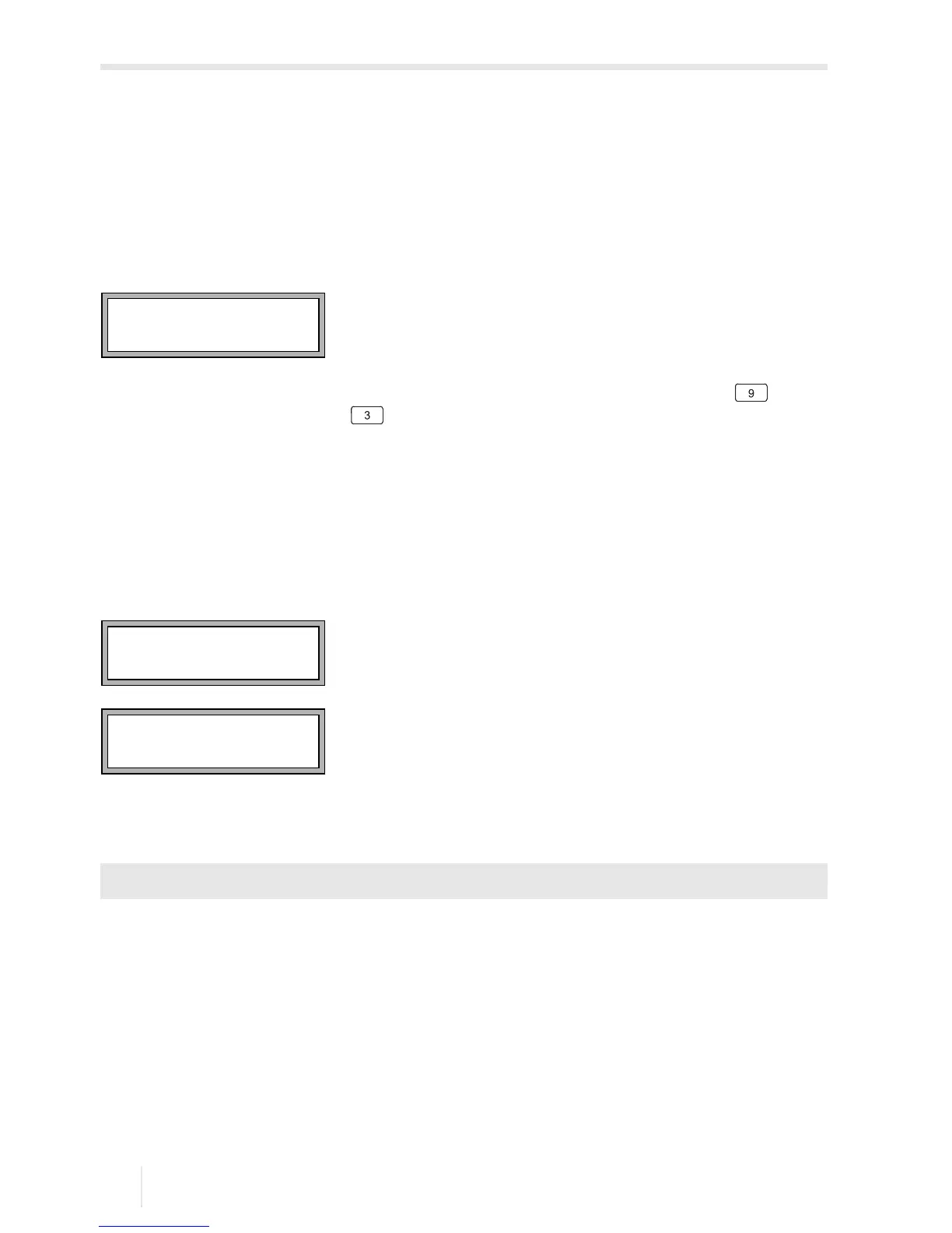
The bar graph S= shows the amplitude of the received signal, see Fig. 9.1.
• Shift one of the transducers slightly within the range of the recommended transducer
distance until the bar graph reaches the max. length (max. 6 squares).
The following quantities can be displayed in the upper line by pressing key and in
the lower line by pressing key , see Fig. 9.2:
• ■<>■=: transducer distance
• time: transit time of the measuring signal in μs
• S=: signal amplitude
• Q=: signal quality, bar graph has to have max. length
If the signal is not sufficient for a measurement, Q= UNDEF will be displayed.
In case of large deviations, check if the entered parameters are correct or repeat the
measurement at a different point on the pipe.
After the precise transducer positioning, the recommended transducer distance is dis-
played again.
• Enter the current (exact) transducer distance.
• Press ENTER.
Repeat the steps for all channels on which a measurement is made. The measurement
will be started automatically.
Fig. 9.1: Diagnostics window
Fig. 9.2: Diagnostics window
Measuring\Channel\...\Transd. Distance\54 mm

 Loading...


