7 Connection
FLUXUS F60* 7.2 FLUXUS *608
67
UMFLUXUS_F60xV5-0EN, 2017-10-16
• Remove the blind plug, see Fig. 7.19.
• Prepare the cable with an M20 cable gland.
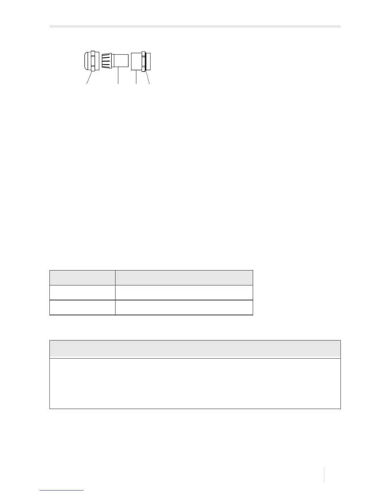
• Push the cable through the cap nut, the compression part and the basic part of the ca-
ble gland, see Fig. 7.19 and Fig. 7.20.
• Insert the cable into the housing.
• Screw the sealing ring side of the basic part into the housing of the power adapter.
• Fix the cable gland by screwing the cap nut onto the basic part of the cable gland.
• Connect the cable to the terminals of the power adapter, see Fig. 7.19 and Tab. 7.5.
• Connect the connector of the power adapter to the socket of the transmitter, see Fig.
7.19.
7.2.2.3 Operation with power supply unit (FLUXUS *608**-F2 only)
• Connect the power supply unit to the socket on the upper side of the transmitter, see
Fig. 7.21.
Fig. 7.20: Cable gland
1 – cap nut
2 – compression part
3 – basic part
4 – gasket ring side of the basic part
Tab. 7.5: Terminal assignment (power adapter)
terminal connection DC
(+) -DC
(-) +DC
→ Use only the supplied power supply unit.
→ The power supply is not protected against moisture. Use it only in dry rooms.
→ The voltage indicated on the power supply unit must not be exceeded.
→ Do not connect a defective power supply unit to the transmitter.

 Loading...


