7 Connection
7.2 FLUXUS *608 FLUXUS F60*
2017-10-16, UMFLUXUSF60xV5-0EN
70
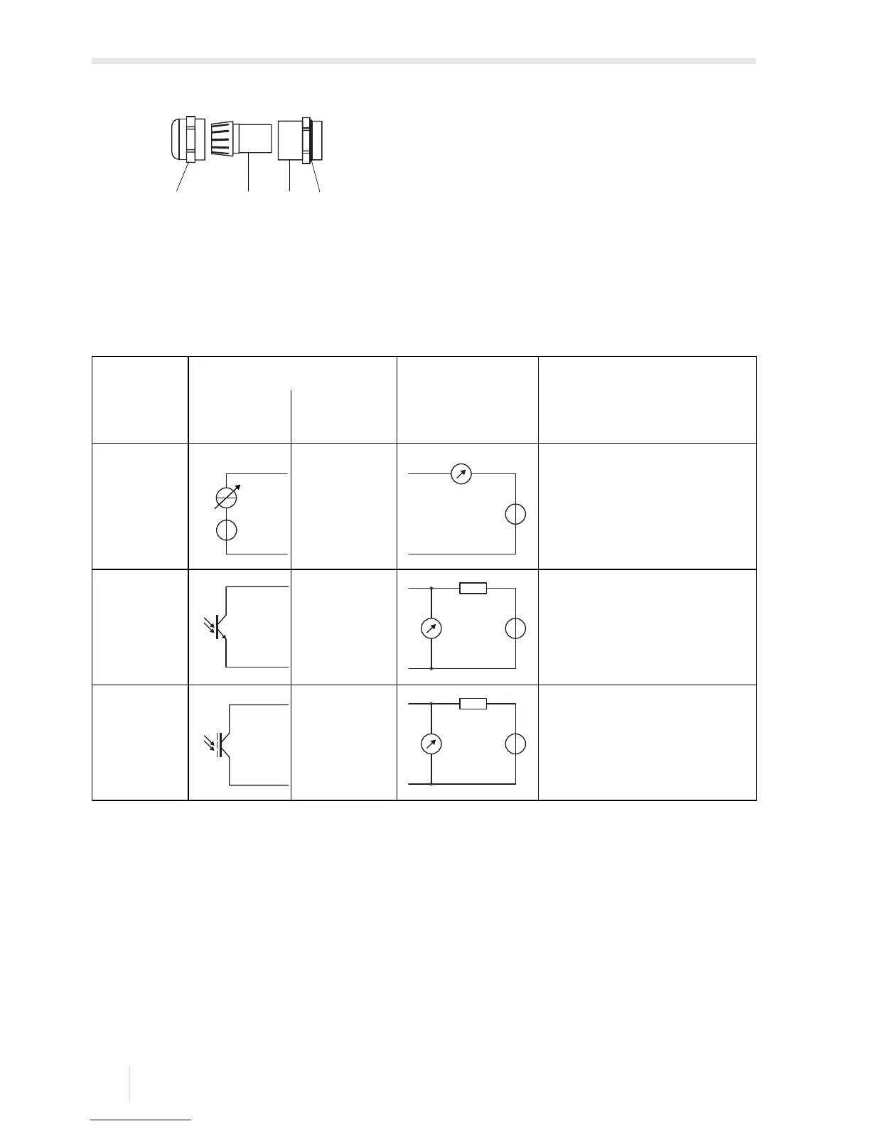
Fig. 7.23: Cable gland
1 – cap nut
2 – compression part
3 – basic part
4 – gasket ring side of the basic part
Tab. 7.6: Circuit of the outputs
output transmitter external circuit remark
internal
circuit
connection
passive
current
output
U
ext
=
4…9 V
U
ext
> 0.021
A
·
R
ext
[Ω] +
4
V
example:
U
ext
= 6 V
R
ext
≤ 90 Ω
frequency
output
U
ext
= 5…24 V
R
c
[kΩ] = U
ext
/I
c
[mA]
I
c
= 1…4 mA
binary
output
(optorelay)
U
ext
≤ 26 V
I
c
≤ 100 mA
The number, type and the connections of the outputs depend on the order.
R
ext
is the sum of all ohmic resistances in the circuit (e.g., resistance of the conductors, resistance
of the amperemeter/voltmeter).

 Loading...


