FLEX-6000 Signature Series - SmartSDR for Windows Software User’s Guide
Page 80
Copyright 2018 FlexRadio Systems. All Rights Reserved.
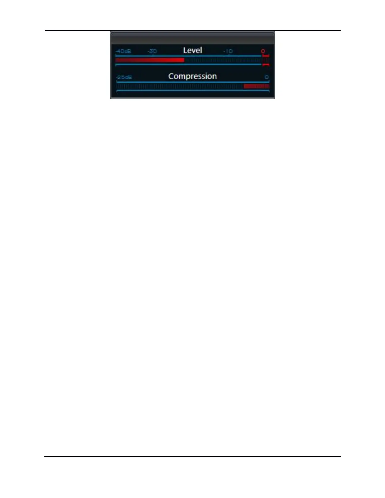
There are two indicator components of the microphone or input Level meter that show the actual
audio input level. The leftmost component is a solid bar indicating the average input level and the
smaller box-like component farther to the right of the average input level bar is the peak level
indicator. The Level meter indicator bars also utilize three colors to visually indicate the input level
range. Signals up to -10 dB are shown in green. Signals levels between from -10 and 0 dB are shown
in yellow. Any signal level that is greater than 0 dB is shown in red.
When setting up your microphone audio for optimal modulation, adjust the input gain so that the
peak level indicator is peaking just BELOW the 0 dB on voice peaks. It is very important that your
peak level indicator never exceed 0 dB and turn red at any time. A red peak level indicator indicates
over-driven or “clipped” input audio levels resulting in audio distortion. The input ALC is active, but
excessive input signal levels may result in input signals that can exceed 0 dB. If you see the peak level
indicator turn red at any time, turn down the audio input level until you no longer see the peak level
indicator turn read.
The compression meter indicates the amount of compression provided by the speech processor
based on the PROC setting and the input gain level. This meter is informational only and is not used
in setting microphone levels.
20.3.2 Operating the Speech Processor
The speech processor implements the W9GR Controlled Envelope Single Sideband (CESSB) peak
limiting algorithm in SSB, AM and FM modes. The controls are highlighted below in the red square.
The processor may be on or off and has three different settings when enabled. In the NOR or normal
setting, the processor provides minimal additional gain and simply prevents audio peaks from
clipping or producing power greater than the set level. In the DX setting, more gain is provided to
the audio to increase the overall sideband envelope which results in a stronger signal that may be
more readily heard at a distance. The DX+ setting adds even more gain increasing your talk power
or “punch” without incurring significant audio distortion. DX+ is most effective if you increase the
low-cut TX filter to between 200-400 Hz to concentrate your talk power in the audio frequency range
that has the greatest intelligibility.

 Loading...