17
Limitorque QX Electronic Actuator FCD LMENIM3314-01 – 06/18
flowserve.com
Step 6
Reconnect incoming power leads L1, L2, L3, and control wiring to the terminal block. Restore power source when
ready for operation.
3.2 Actuator Removal with Type A1/A1E Base (Thrust) – QXM only
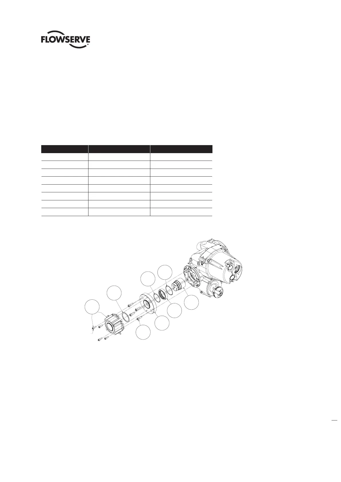
3.2.1 Optional Thrust Base Assembly QX-1 & 2
Table 3.2 - Optional Thrust Base Assembly
ITEM NUMBER DESCRIPTION QTY.
16-10 TORQUE NUT 1
16-11 BUSHING 1
16-12 O'-RING 1
16-13 O'-RING 1
16-14 ADAPTER PLATE 1
16-15 SOCKET HEAD CAP SCREWS 4
16-16 SPACER, PILOT, ISO ONLY 1
16-17 THRUST BASE ASSEMBLY 1
Figure 3.3 - Optional Thrust Base Assembly
3.2.2 Optional thrust base assembly removal.
Step 1
Remove the four (4) screws (# ) and remove the thrust base subassembly (#16-17) by sliding the base down. If base
is ISO remove the spacer (pilot) (#16-16).
Step 2
Remove the four (4) screws (# 16-15) and remove the adapter plate (#16-14) and torque nut (#16-10). Item (#16-11)
bushing is pressed into adapter plate and cannot be removed. The torque nut is held in place by the unit drive sleeve
and the bushing (#16-11).
16-10
16-12
16-11
16-13
16-14
16-16
ISO THRUST BASE ONLY
16-15
16-17
SOC HD CAP SCREWS
ARE PART OF THRUST
BASE SUBASSEMBLY
16-10
Soc hd cap screws
are part of thrust
base subassembly
16-11
16-14
15-15
16-12
16-13
16-16
16-17
ISO thrust base only