57
Limitorque QX Electronic Actuator FCD LMENIM3314-01 – 06/18
flowserve.com
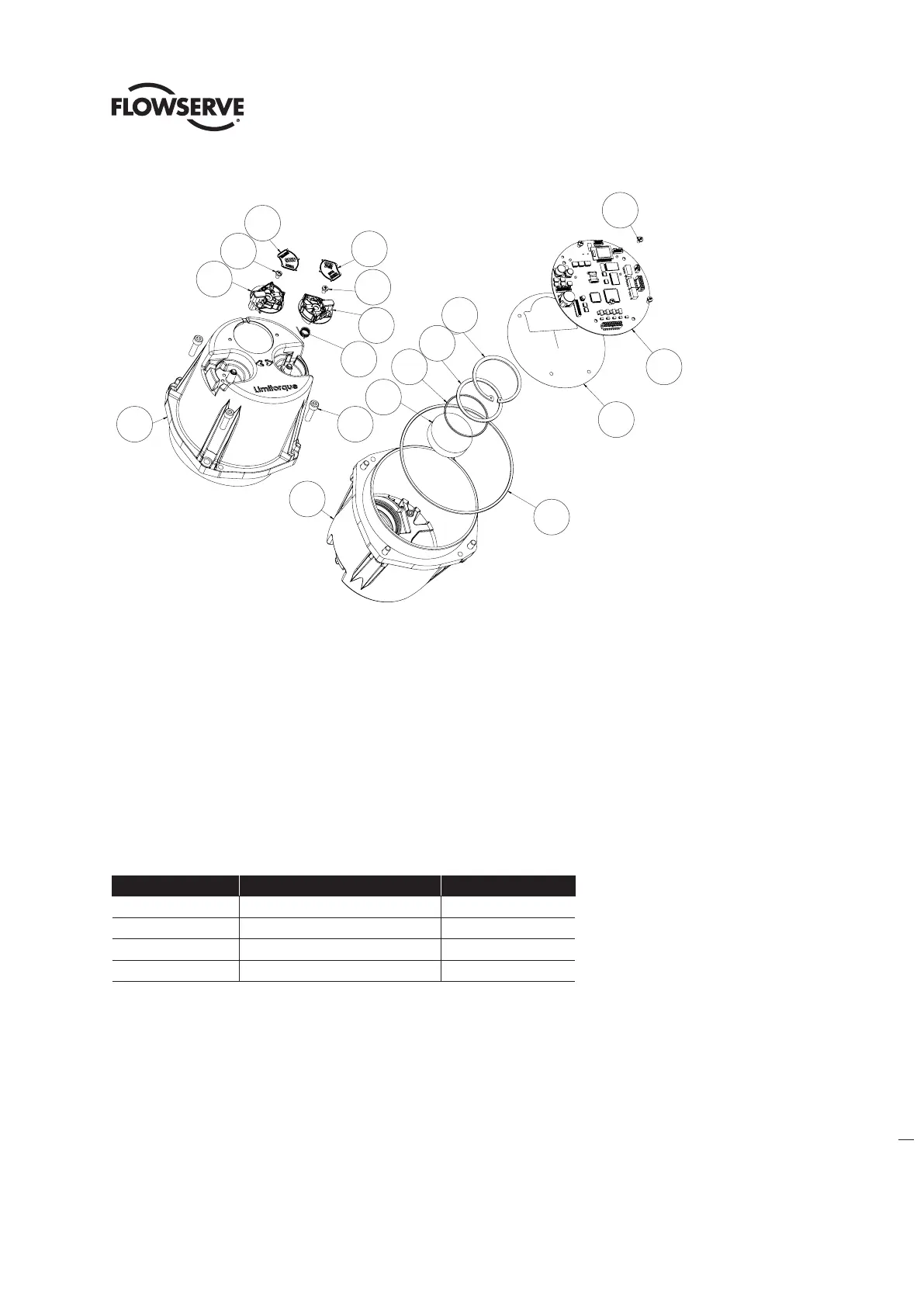
Figure 6.4 - Controls Cover Subassembly
6.2.2 Controls Cover Subassembly Remounting
Step 1
Lightly lubricate ‘O’-ring (#7-21) and install around controls cover spigot/pilot (#7-17). Connect all wiring (See section
7 for wiring connection locations). Slide controls cover spigot/pilot into the unit housing insuring not to pinch wiring.
Step 2
Fit the 4 screws (#15-6) into controls cover mounting holes and tighten to torque in section 2.
6.3 Control Modules
Table 6.5 - Control Module Assembly
ITEM NUMBER DESCRIPTION QTY.
14-8 CONTROLS SUBASSEMBLY 1
14-9 SOCKET HEAD CAP SCREWS 3
14-11 BRACKET, CONNECTOR RETAINER 1
14-12 SOCKET HEAD CAP SCREWS 1
7-7
7-14
7-6
7-6
7-3
7-4
7-12
1-46
7-17
1-49
7-20
7-19
7-2
7-18
8-24
7-44
7-21
7-17
7-4
7-6
7-14
7-7
7-6
7-3
7-2
7-17
7-17
1-46
7-18
7-21
1-49
8-24
7-12
7-19
7-20
7-44