45
Limitorque QX Electronic Actuator FCD LMENIM3314-01 – 06/18
flowserve.com
4.10.1 Optional Small Baseplate Removal.
Step 1
QX-1 & 2, F/FA-10 and QX-3 thru 5 F/FA-12 and -14. Using a M3 hex key forQX-1 & 2 or M5 hex key for QX-3, 4 & 5,
remove the M4 or M6 screws (#13-7) and remove torque nut (#13-6).
QX-1 & 2, F/FA-05 or -07, QX-3 thru 5 F/FA-10.
Remove small baseplate per Section 4-6-4. Using a M3 hex key, QX-1 & 2 or M5 hex key for QX-3, 4 & 5, remove the
M4 or M6 screws (#13-7) and remove torque nut (#16-7).
4.10.2 Optional Small Baseplate Remounting.
Step 1
NOTE: Torque nut may be mounted in 1 of 4 positions (every 90°) on QX-1 & 2 and 1 of 8 positions (every 45°) on the
QX-3 thru 5. Make sure the torque nut is in the position needed.
Slide torque into drive sleeve aligning pilot and lugs, Place screws in torque nut holes and tighten. Remount baseplate.
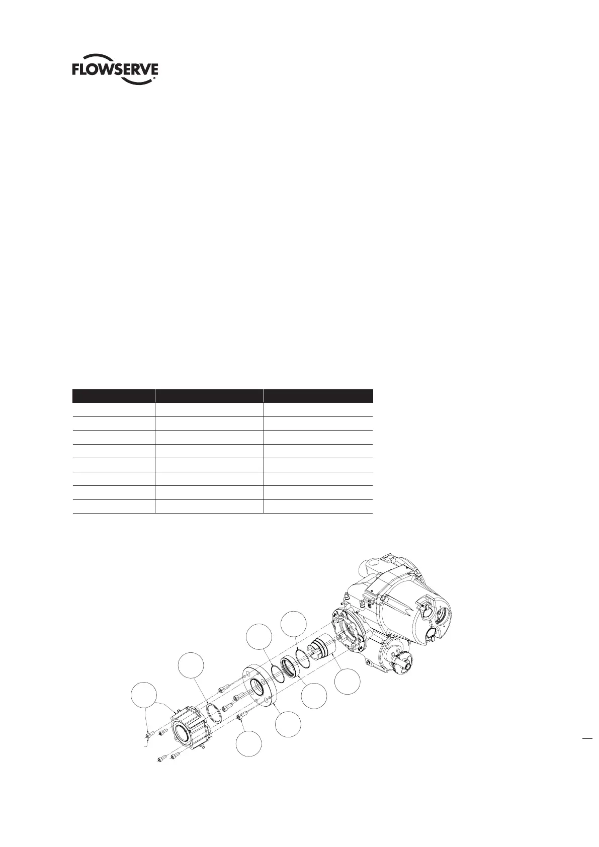
4.11 Optional Thrust Base Assembly QX-1 & 2.
Table 4.23 - Optional Thrust Base Assembly
ITEM NUMBER DESCRIPTION QTY.
16-10 TORQUE NUT 1
16-11 BUSHING 1
16-12 O'-RING 1
16-13 O'-RING 1
16-14 ADAPTER PLATE 1
16-15 SOCKET HEAD CAP SCREWS 4
16-16 SPACER, PILOT, ISO ONLY 1
16-17 THRUST BASE ASSEMBLY 1
Figure 4.27 - Optional Thrust Base Assembly QXM Only
16-10
16-12
16-11
16-13
16-14
16-16
ISO THRUST BASE ONLY
16-15
16-17
SOC HD CAP SCREWS
ARE PART OF THRUST
BASE SUBASSEMBLY
16-12
16-13
16-10
16-11
16-14
16-15
16-17
16-16
Soc hd cap screws
are part of thrust
base subassembly
ISO thrust base only