Limitorque QX Electronic Actuator FCD LMENIM3314-01 – 06/18
52
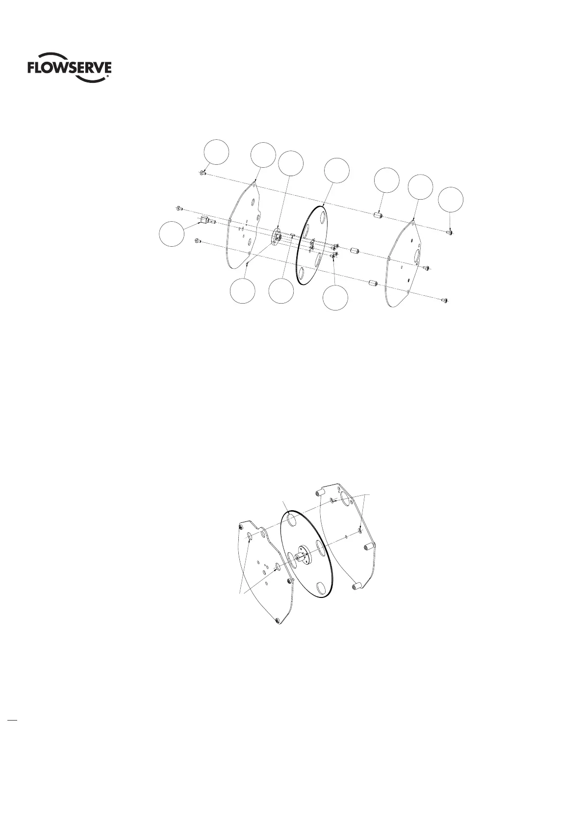
Figure 5.6 - 20-Turn Spur Gear Subassembly (Item 17-2)
5.2.2 Multi Turn Encoder Remounting
Step 1
Slide the encoder spur assembly (#17-2) into housing thru housing controls area bore and down over the multi turn
encoder shaft pinion. Align spur assembly bottom plate to top encoder ball bearing (#1-5), the dowel pin (#17-1) while
also aligning the spur assembly big gear to the encoder shaft pinion.
NOTE: for the 20 turn assembly the big spur gear slots must be aligned with the holes in the top and bottom plates to
insert the two (#17-3) screws. Figure 5.7 for orientation view.
Insert the two screws (#17-3) and tighten.
Firgure 5.7 - 20-Turn Gear Slot Orientation View
Step 2
Place spacers (#17-4) (QX-1 &2 only) in place in-between the spur assembly bottom plate and the housing lower pads,
Note that this step can be done before step 1. Insert screws (#17-5) and tighten.
Step 3
Slide the encoder assembly into housing and down over encoder shaft (#2) on multi turn spur assembly aligning the
rotor (#2) of the encoder to the encoder shaft OD, flats and encoder standoff pin to the top spur assembly alignment
hole (See Figure 5.3) for reference.
1
2
6
4
8
10
10
9
7
3
5
SEE NOTE 3
TOP PLATE
ACCESS HOLES
2 PLACES
SPUR GEAR SLOTS
4 PLACES @ 90
BOTTOM PLATE
MOUNTING HOLES
2 PLACES
5
7
4
10
9
8
6
3
1
2
10
See note 3
Bottom plate
Mounting holes
2 Places
Spur gear slots
4 Places @ 90°
Top plate
Access holes
2 Places