Limitorque QX Electronic Actuator FCD LMENIM3314-01 – 06/18
38
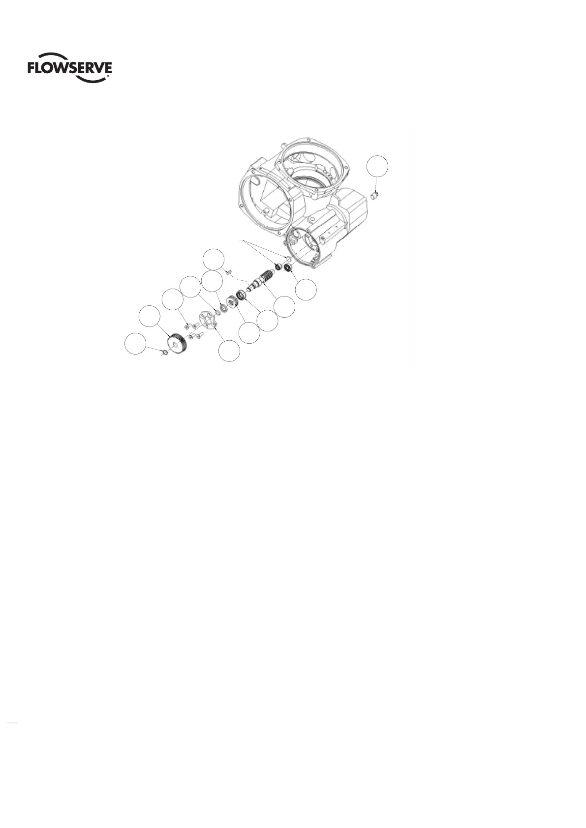
Figure 4.20 - Worm Shaft
4.7.1 Worm Shaft Assembly Removal.
Step 1
c WARNING: Potential to operate while dangerous mechanical parts are exposed during subassembly removal.
To prevent injury, turn off all power sources to actuator before removing top-mounted handwheel assembly.
Power sources may include main power or control power.
Using retaining ring pliers remove retaining ring (#2-11) and then remove gear (#2-10) and key (#2-9). Using M4 hex
key (QX-1 & 2) or M6 hex key (QX-3 thru 5) remove M6 or M10 screws (#2-7) and remove plate (#2-6).
Step 2
Remove pipe plug (#13-5) from back of housing and worm shaft underneath motor. Remove base plate (#3) so drive
sleeve and stops are visible (See section 4-6-1). Rotate worm shaft so the drive sleeve is in mid position. Being careful
not to hit the threads of the pipe tap, hammer out the worm shaft hitting the flat washer (#1-8) that is in back of the
worm shaft.
NOTE: The drive sleeve will rotate when knocking out worm shaft. Be sure that the drive sleeve is off of stops or
damage to drive sleeve, stops and/or housing could accrue.
Step 3
If replacing bearings but not worm shaft remove round retaining ring (#2-5) to remove thrust bearing (#2-3) and
needle bearing (#2-2) from worm shaft.
If replacing worm shaft, thrust bearing and needle bearing this step is not needed.
4.7.2 Worm Shaft Assembly Replacement.
a
CAUTION: Flowserve Limitorque recommends that the factory be contacted at 434-528-4400 to arrange
replacement of a QX worm shaft at an authorized service center. Special tools are required for replacement.
Step 1
(Special tools required, contact factory for ordering information)
13-5
2-1
2-9
2-2
2-3
2-4
2-5
2-6
2-7
2-10
2-11
2-8
INSTALLED BEFORE DRIVE SLEEVE ASSEMBLY
SEE SECTION 4-7
DRIVE SLEEVE ASSEMBLY FLAT WASHER (1-8)
AND SMALL NEEDLE BEARING (1-9)
2-9
13-5
2-8
2-1
2-2
2-3
2-4
2-5
2-7
2-10
2-11
2-6
Installed before drive sleeve assembly
see section 4-7
Drive sleeve assembly at washer (1-8)
and small needle bearing (1-9)