49
Limitorque QX Electronic Actuator FCD LMENIM3314-01 – 06/18
flowserve.com
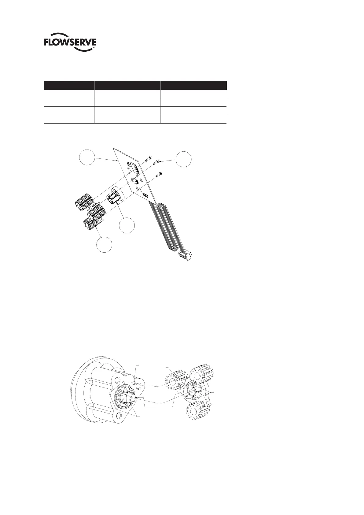
Table 5.2 - Encoder Subassembly, Item 14-1
ITEM NUMBER DESCRIPTION QTY.
1 ENCODER BOARD 1
2 ROTOR 1
3 STANDOFF 1
4 SELF TAP OVAL HEAD SCREWS 4
Figure 5.2 - Encoder To Subassembly, Item 14-1
5.1.2 90 Degree Encoder Remounting
Step 1
Slide the encoder assembly into housing and down over encoder shaft (#1-6) aligning the rotor (#2) of the encoder
to the encoder shaft OD, flats, encoder standoff ID to encoder top ball bearing (#1-5) and encoder standoff pin to housing
alignment hole (See Figure 5.3 - Encoder To Unit Assembly View).
NOTE: The encoder rotor can only be mated to the encoder shaft in one position. The encoder shaft has 3 flats that must
align correctly to the encoder rotor ID and ribs.
Figure 5.3 - Encoder To Unit Assembly View
Step 2
Install the three M4 screws thru encoder and standoff assembly (#14-2) and tighten. Take note not to over tighten.
Step 3
Reconnect encoder ribbon cable to motor controller board. (See Section 7.1 for connector position on motor control board)
4
2
3
1
PIN TO HSG
ALIGNMENT HOLE
SHAFT OD TO
ROTOR ID
ROTOR RIBS FOR
SHAFT FLATS
SHAFT FLATS
3 SIDES
1
4
2
3
PIN TO HSG
ALIGNMENT HOLE
SHAFT OD TO
ROTOR ID
ROTOR RIBS FOR
SHAFT FLATS
SHAFT FLATS
3 SIDES
Rotor ribs for
Shaft ats
Shaft ats
3 Sides
Pin to hsg
alignment hole
Shaft OD to
Rotor ID